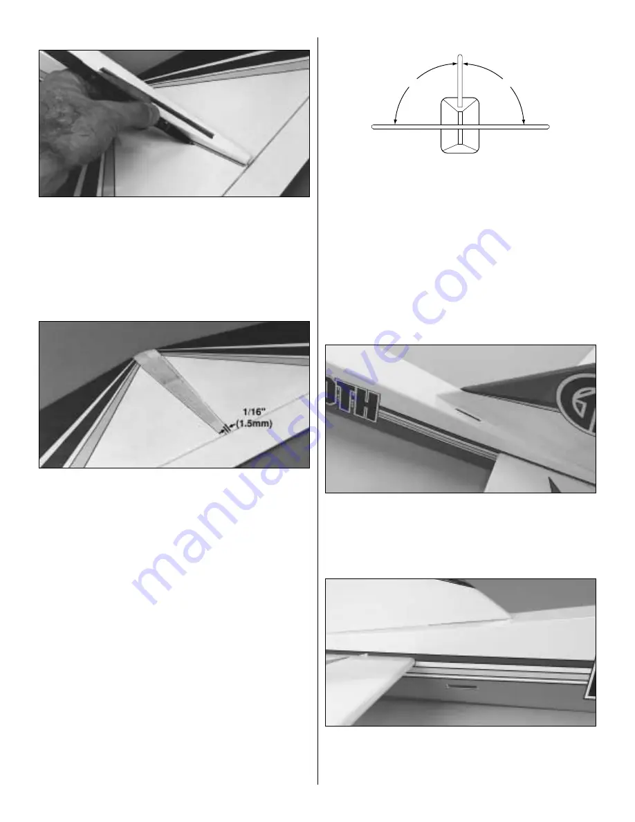
MARK THE STABILIZER LOCATION
❍
8. With the stabilizer properly aligned, use a felt-tip pen to trace
around the tail of the airplane on the top and bottom of the
horizontal stabilizer.
REMOVE THE CENTER COVERING
❍
9. Remove the stabilizer and draw two additional lines, on the top
and bottom, 1/16" (1.5mm) inside the lines drawn in the previous
step. Next, carefully cut through the covering using a new #11 knife
blade at the inside lines and remove the covering from the center. Do
not cut the wood under the covering! This will seriously weaken the
stabilizer and could easily cause the stabilizer to break in flight. If
the stab breaks, the plane has a very good chance of crashing. It is
best to be very careful when making this cut not to cut into the
wood. The covering does need to be removed from the center of the
stab, or the bond between the stabilizer base and stabilizer will be
insufficient and the stab may simply come off in flight.
INSTALL THE STABILIZER
❍
10. Mix 1/4oz (7ml) of 30-minute epoxy. Using a mixing stick,
place glue inside the horizontal stabilizer slot on all sides, and a
good layer of epoxy on the stabilizer base. Place a thin layer of epoxy
on the stabilizer in the area where the covering was removed. Insert
the stabilizer into the slot from the rear and check the alignment.
Wipe off any epoxy that squeezes out using a paper towel and
rubbing alcohol. Recheck the alignment several times while the
epoxy cures.
INSTALL THE VERTICAL FIN
❍
11. Test fit the vertical fin into the slot on the top of the fuselage.
Sand the edges of the slot if necessary for a snug fit. When fit
properly the bottom of the vertical fin will rest on the top of the
horizontal stabilizer. Remove the fin and mix up 1/4oz (7ml) of
30-minute epoxy. Using a mixing stick, apply epoxy to the top of the
stabilizer through the slot. Apply epoxy to the sides and bottom of
the fin base that have the balsa wood exposed. Insert the fin into the
slot. Check to make sure that the fin is perpendicular to the stabilizer
when viewed from the rear of the airplane. (Use the sketch as a guide
for checking the alignment.) Check this alignment several times as
the epoxy cures. (You may find it beneficial to hold the fin in place
using masking tape until the epoxy has cured.)
CUT THE RUDDER PUSHROD EXIT
❍
12. The precut rudder pushrod exit hole is located on the top of
the fuselage on the left side of the fin. Locate the exit hole by gently
running your finger along the top of the fuselage over the covering.
It should be beside the rudder as shown in the photo. Use a hobby
knife to remove the covering from the rudder pushrod exit hole.
CUT THE ELEVATOR PUSHROD EXIT
❍
13. The precut elevator pushrod exit hole is located on the right
side of the fuselage. Locate the exit hole by gently running your
finger along the side of the fuselage over the covering. It should be
slightly in front of the elevator as shown in the photo. Use a hobby
knife to remove the covering from the elevator pushrod exit hole.
90˚
90˚
9


