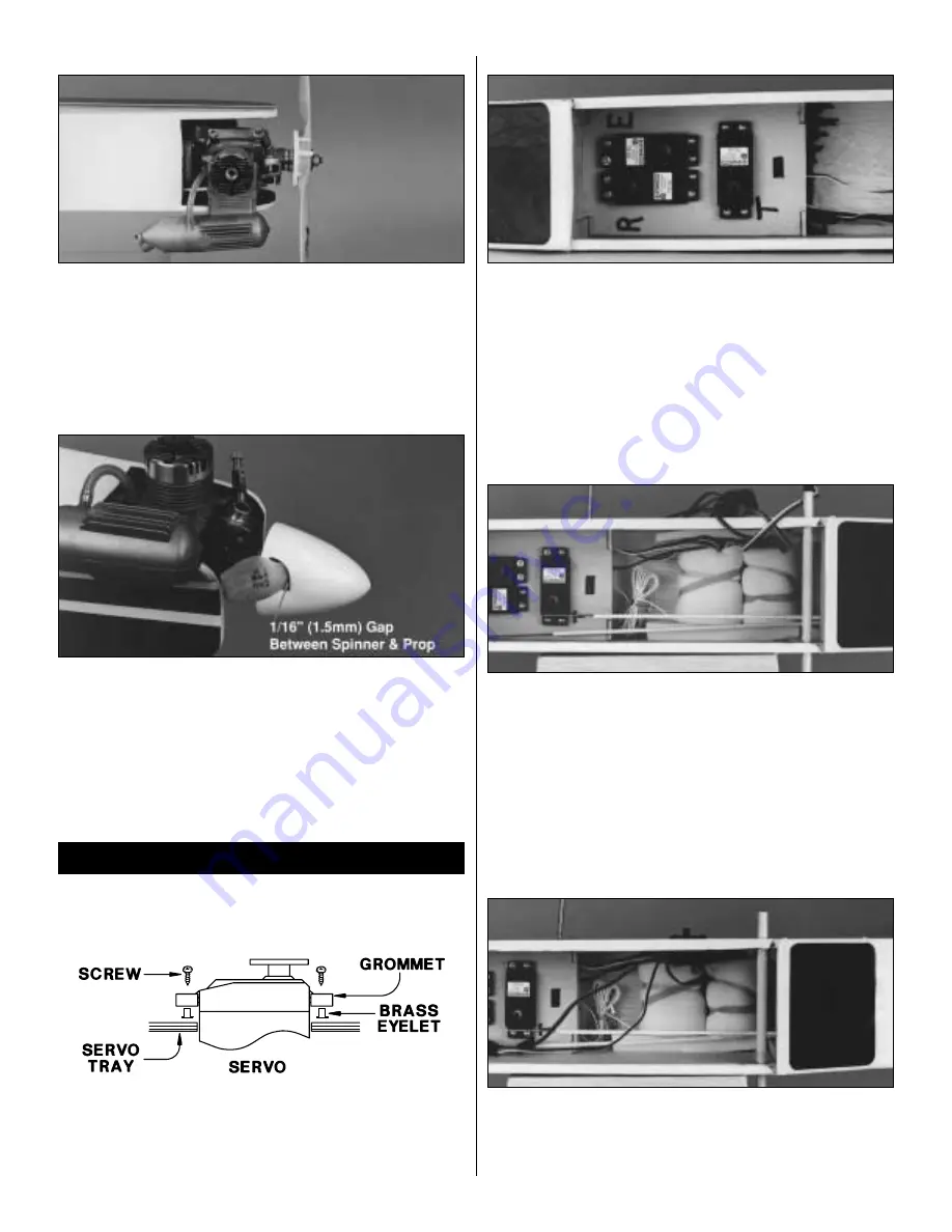
ATTACH THE FUEL LINES
❍
6. Attach the fuel lines to the engine. The line marked with the “V”
for vent should be attached to the muffler. The other line will be
attached to the carburetor. Make sure there are no sharp bends in the
lines. If so, carefully shorten the lines to allow for a smooth flowing
bend to the appropriate fitting of the engine.
INSTALL THE SPINNER
❍
7. Trim the spinner cone propeller slots if necessary so there is at
least a 1/16" (1.5mm) gap between the cone and the propeller. Once
satisfied with the fit, attach the cone with the screws provided. Be
careful not to overtighten these screws. They are threaded into plastic
which can strip out easily if they are over tightened.
PREPARE THE SERVOS
❍
1. Install the rubber grommets and brass eyelets, included with
your radio system, onto the four servos. Use the sketch to assist in the
installation of these items.
INSTALL THE SERVOS IN THE FUSELAGE
❍
2. Route the servo wires forward. Drill 1/16" (1.5mm) pilot holes
for the servo mounting screws. Install the servos into the tray as
shown using the screws included with the radio system. It may be
necessary to enlarge the openings for the servos. The arms should be
removed from the servos during the installation. The servos in the
photo are marked as to which is rudder (R), elevator (E) and throttle
(T) to help in getting them plugged into the receiver correctly.
RECEIVER AND BATTERY INSTALLATION
❍
3. Following the radio system‘s instruction manual, plug the three
servos into the receiver. Next, plug a servo extension into the aileron
channel of the receiver. Finally, plug the switch harness into the
receiver. Wrap the receiver and battery pack in foam rubber
(HCAQ1050) using rubber bands or masking tape to hold the foam
in position. Install the battery and receiver into the fuselage. The
battery should be located forward of the receiver.
INSTALL THE SWITCH
❍
4. Remove the covering from the square opening on the left side
of the fuselage, opposite of the engine exhaust. Position the face
plate so that it is centered over the opening. Drill two 1/16" (1.5mm)
holes in the locations for the screws through the fuselage. Attach the
switch using the screws that are included with the switch.
RADIO INSTALLATION
13


