4-14
T2100 Series
4.
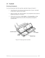
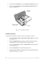
Carefully lift up the
keyboard
to expose the
keyboard connector
(Figure 4-11).
5.
Disconnect the
keyboard cable
from
pressure-plate connector (PJ14)
on the
system board (Figure 4-11).
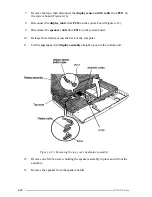
Figure 4-11 Removing the keyboard
Installing the Keyboard
To install the keyboard, follow the steps below and refer to Figures 4-10 and 4-11.
1.
Connect the
keyboard cable
to
pressure plate connector (PJ14)
on the system
board (Figure 4-11).
2
.
Replace the
keyboard
fitting the extensions on the back of the keyboard into
corresponding holes on the computer and lay the keyboard in place.
3.
Insert the
keyboard brace
between the
AccuPoint cable
and under side of the
keyboard (Figure 4-10).
4.
Secure the
five latches
on the keyboard base (Figure 4-10).
5.
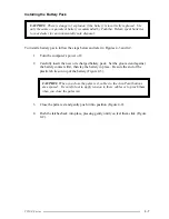
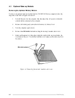
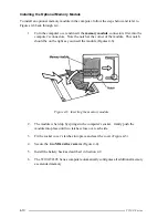
Install the optional PCMCIA card, optional memory module and battery pack as
described in Sections 4.4, 4.3 and 4.2.
Содержание T2100 Series
Страница 5: ...T2100 Series 1 5 Figure 1 2 T2100 T2105 Series system unit configuration ...
Страница 25: ...T2100 Series 2 3 Figure 2 1 Troubleshooting flowchart 1 2 ...
Страница 114: ...3 64 T2100 Series ...
Страница 167: ...T2100 Series B 1 Appendix B Board Layout B 1 FHVSY System Board Figure B 1 FHVSY system board front ...
Страница 168: ...B 2 T2100 Series Figure B 2 FHVSY system board back ...
Страница 180: ...C 10 T2100 Series ...
Страница 181: ...T2100 Series D 1 Appendix D USA Display Codes Table D 1 USA display codes ...
Страница 182: ...D 2 T2100 Series ...
Страница 190: ...F 2 T2100 Series F 3 German GR Keyboard Figure F 3 GR keyboard F 4 French FR Keyboard Figure F 4 FR keyboard ...
Страница 191: ...T2100 Series F 3 F 5 Spanish SP Keyboard Figure F 5 SP keyboard F 6 Italian IT Keyboard Figure F 6 IT keyboard ...
Страница 196: ...H 2 T2100 Series ...
Страница 198: ...I 2 T2100 Series ...


