4-16
T200, T200CS
4.7
Upper System Board • Backup Battery • RTC Battery
Removing the Upper System Board, Backup Battery and RTC Battery
CAUTION
: RTC memory data will be erased when the RTC battery connector is
disconnected. Before removing the RTC battery, memorize the information.
To remove the computer’s upper system board, backup battery, and RTC battery, follow the steps
below and refer to Figures 4-9 and 4-10.
1.
Turn off the power to the computer. Disconnect the AC adapter, power cord and
all external cables connected to the computer.
2.
Remove the battery pack, optional memory card, optional PCMCIA cards, HDD,
and back cover as described in sections 4.2, 4.3, 4.4, 4.5 and 4.6.
3.
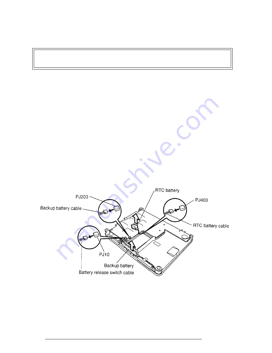
Peel back the protective tape and reflect the insulator away, then disconnect the
backup battery cable
from
PJ203
, and lift out the
backup battery
(Figure 4-9).
4.
Reflect the insulator away, then disconnect the
RTC battery cable
from
PJ403
, and
lift out the
RTC battery
(Figure 4-9).
5.
Disconnect the
battery release switch cable
from
PJ10
(Figure 4-9).
Figure 4-9 Removing the Backup Battery and RTC Battery
Содержание T200
Страница 23: ...T200 T200CS 2 3 Figure 2 1 Troubleshooting Flowchart 1 2 ...
Страница 24: ...2 4 T200 T200CS Figure 2 1 Troubleshooting Flowchart 2 2 ...
Страница 82: ...3 32 T200 T200CS ...
Страница 90: ...3 40 T200 T200CS Head XX Sector XX Model name ...
Страница 153: ...T200 T200CS B 1 Appendix B Board Layout B 1 Upper System Board FOGSD2 Figure B 1 Upper System Board FOGSD2 Front ...
Страница 154: ...B 2 T200 T200CS Figure B 2 Upper System Board FOGSD2 Back ...
Страница 156: ...B 4 T200 T200CS B 2 Lower System Board FOGSU2 Figure B 3 Lower System Board FOGSU2 Front ...
Страница 157: ...T200 T200CS B 5 Figure B 4 Lower System Board FOGSU2 Back ...
Страница 170: ...T200 T200CS D 1 Appendix D USA Display Codes Table D 1 USA Display Codes ...


