


– 128 –
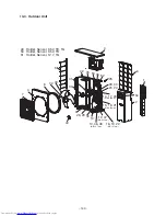
Discharge port cabinet
Rear cabinet
Rear cabinet
Partition plate
Fin guard
Heat exchanger
Motor base
Inverter assembly
Inverter assembly
Rear cabinet
Rear cabinet
Rear cabinet
Inverter assembly
Rear cabinet
No.
2
3
Part name
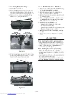
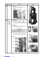
Discharge
port cabinet
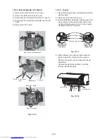
Rear cabinet
Procedure
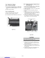
1. Detachment
1) Perform work of Detachment 1 of
1
.
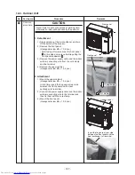
2) Take off screws for the discharge port cabinet
and the partition plate. (ST1T Ø4 × 8, 3 pcs.)
3) Take off screws for the discharge port cabinet
and the bottom plate.
(Hexagonal screw Ø4 × 10, 2 pcs.)
4) Take off screws for the discharge port cabinet
and the motor base. (ST1T Ø4 × 8, 2 pcs.)
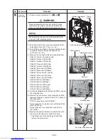
5) Take off screw for the discharge port cabinet
and the heat exchanger. (ST1T Ø4 × 8, 1 pc.)
6) Take off screws for the discharge port cabinet
and the fin guard.
(Hexagonal screw Ø4 × 10, 2 pcs.)
1. Detachment
1) Perform work of Detachment 1 of
1
.
2) Take off screw for the rear cabinet and the
valve fixed board.
(Hexagonal screw Ø4 × 10, 2 pcs.)
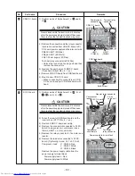
3) Take off screw for the rear cabinet and the
anchor board.
(Hexagonal screw Ø4 × 10, 1 pc.)
4) Take off screws for the rear cabinet and the
heat exchanger.
(Hexagonal screw Ø4 × 10, 2 pcs.)
5) Remove the rear cabinet by shifting it
obliquely backward and upward.
Remarks
Содержание RAS-5M34UAV-E
Страница 35: ... 35 4 2 Outdoor Unit RAS 5M34UAV E ...
Страница 37: ... 37 5 2 Outdoor Unit RAS 5M34UAV E POWER SUPPLY CIRCUIT ...


