11-1. First Confirmation
11-1-1. Confirmation of Power Supply
Confirm that the power breaker operates (ON) normally.
11-1-2. Confirmation of Power Voltage
Confirm that power voltage is AC 220–230–240 ± 10%.
If power voltage is not in this range, the unit may not operate normally.
11-1-3. Operation Which is not a Trouble (Program Operation)
For controlling the air conditioner, the program operations are built in the microcomputer as described in the
following table.
If a claim is made for running operation, check whether or not it meets to the contents in the following table.
When it does, we inform you that it is not trouble of equipment, but it is indispensable for controlling and main-
taining of air conditioner.
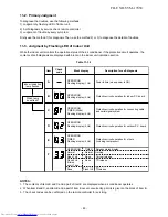
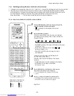
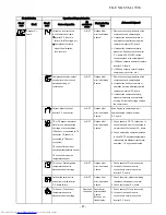
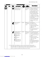
Table 11-1-1
No.
1
2
3
4
5
Operation of air conditioner
When power breaker is turned “ON”, the
operation indicator (white) of the indoor
unit flashes.
Compressor may not operate even if the
room temperature is within range of
compressor-ON.
In Dry and ECO mode, FAN (air flow)
display does not change even though FAN
(air flow select) button is operated.
In AUTO mode, the operation mode is
changed.
Description
The OPERATION lamp of the indoor unit flashes when
power source is turned on. If [ ] button is
operated once, flashing stops.
(Flashes also in power failure)
The compressor does not operate while compressor
restart delay timer (3-minutes timer) operates.
The same phenomenon is found after power source has
been turned on because 3-minutes timer operates.
The air flow indication is fixed to [AUTO].
The compressor motor speed may decrease by high-
temp. release control (Release protective operation by
temp.-up of the indoor heat exchanger) or current
release control.
After selecting Cool or Heat mode, select an operation
mode again if the compressor keeps stop status for 15
minutes.
In HEAT mode, the compressor motor
speed does not increase up to the maxi-
mum speed or decreases before the
temperature arrives at the set temperature.
FILE NO. SVM-17050
- 82 -
Содержание RAS-25PAVPG-ND
Страница 18: ...5 WIRING DIAGRAM FILE NO SVM 17050 18 ...

