12. HOW TO REPLACE THE MAIN PARTS
WARNING
• Since high voltages pass through the electrical parts, turn off the power without fail before proceeding with
the repairs.
Electric shocks may occur if the power plug is not disconnected.
• After the repairs have been completed (after the front panel and cabinet have been installed), perform a
test run, and check for smoking, unusual sounds and other abnormalities.
If this check is omitted, a fire and/or electric shocks may occur.
Before proceeding with the test run, install the front panel and cabinet.
• Ensure that the following steps are taken when doing repairs on the refrigerating cycle.
1. Do not allow any naked flames in the surrounding area.
If a gas stove or other appliance is being used, extinguish the flames before proceeding.
If the flames are not extinguished, they may ignite any oil mixed with the refrigerant gas.
2. Do not use welding equipment in an airtight room.
Carbon monoxide poisoning may result if the room is not properly ventilated.
3. Do not bring welding equipment near flammable objects.
Flames from the equipment may cause the flammable objects to catch fire.
•
If keeping the power on is absolutely unavoidable while doing a job such as inspecting the cir-
cuitry, wear rubber gloves to avoid contact with the live parts.
Electric shocks may be received if the live parts are touched.
High-voltage circuits are contained inside this unit.
Proceed very carefully when conducting checks since directly touching the parts on the control circuit
board may result in electric shocks.
12-1.
Indoor Unit
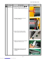
Front panel
1))
St
op operation of the air conditioner
and turn off its main power supply.
2))
O
pen the air inlet grill, push the arm
toward the outside, and remove the grill.
3))
Remove the left and the right air filters.
4)
R
em
ove the fixing screws
(5 pcs.)
5)
O
pen LOUVER-HR as the picture
then pull down and pull outward
PANEL-FR (R) and PANEL-FR(L).
as picture
No.
Part name
Work procedure
Remarks
1
5 Screws
FILE NO. SVM-17050
- 106 -
Содержание RAS-25PAVPG-ND
Страница 18: ...5 WIRING DIAGRAM FILE NO SVM 17050 18 ...

