High Wall, Heat Pump Type
Service Manual
15
Toshiba
Flare processing procedures and precautions
1)
Cutting the Pipe
By means of a pipe cutter, slowly cut the pipe so that it is not deformed.
2)
Removing Burrs and Chips
If the flared section has chips or burrs, refrigerant leakage may occur.
Carefully remove all burrs and clean the cut surface before installation.
3)
Insertion of Flare Nut
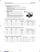
Table 2-2-3 Dimensions related to flare processing for R410A
Table 2-2-4 Dimensions related to flare processing for R22
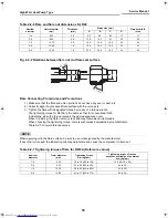
Table 2-2-5 Flare and flare nut dimensions for R410A
4)
Flare Processing
Make certain that a clamp bar and copper pipe have been
cleaned.
By means of the clamp bar, perform the flare processing
correctly.
Use either a flare tool for R410A or conventional flare tool.
Flare processing dimensions differ according to the type of flare
tool. When using a conventional flare tool, be sure to secure
“dimension A” by using a gauge for size adjustment.
Fig. 2-2-1
Flare processing dimensions
Nominal
diameter
Outer
diameter
(mm)
Thickness
(mm)
A (mm)
Flare tool for R410A
clutch type
Conventional flare tool
Clutch type
Wing nut type
1/4
6.35
0.8
0 to 0.5
1.0 to 1.5
1.5 to 2.0
3/8
9.52
0.8
0 to 0.5
1.0 to 1.5
1.5 to 2.0
1/2
12.70
0.8
0 to 0.5
1.0 to 1.5
2.0 to 2.5
5/8
15.88
1.0
0 to 0.5
1.0 to 1.5
2.0 to 2.5
Nominal
diameter
Outer
diameter
(mm)
Thickness
(mm)
A (mm)
Flare tool for R22
clutch type
Conventional flare tool
Clutch type
Wing nut type
1/4
6.35
0.8
0 to 0.5
0.5 to 1.0
1.0 to 1.5
3/8
9.52
0.8
0 to 0.5
0.5 to 1.0
1.0 to 1.5
1/2
12.70
0.8
0 to 0.5
0.5 to 1.0
1.5 to 2.0
5/8
15.88
1.0
0 to 0.5
0.5 to 1.0
1.5 to 2.0
Nominal
diameter
Outer diameter
(mm)
Thickness
(mm)
Dimension (mm)
Flare nut width
(mm)
A
B
C
D
1/4
6.35
0.8
9.1
9.2
6.5
13
17
3/8
9.52
0.8
13.2
13.5
9.7
20
22
1/2
12.70
0.8
16.6
16.0
12.9
23
26
5/8
15.88
1.0
19.7
19.0
16.0
25
29
A
ØD
+00A08-010_01EN_SVM_HighWallHeatPump.book Page 15 Wednesday, March 4, 2009 11:22 AM


