– 94 –
✻
✻
✻
✻
✻
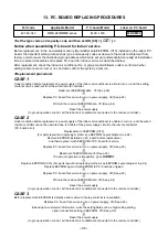
3 Write-in operation of setting contents to EEPROM
(EEPROM setting contents mounted on the service P.C. board are those at shipment from factory.)
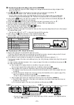
1) Push
SET
+
CL
+
TEST
buttons concurrently for 4 seconds or more on the remote controller.
1
(Corresponded to numbers in p.94. Remote controller operation diagram) (
ALL
is displayed for UNIT No.)
In this time, the item code (DN) displays
10
. The fan of the indoor air conditioner operates.
2) Using TEMP
/
buttons, the item code (DN) is increased / decreased one by one.
3
3) Firstly set type and capacity of the indoor air conditioner.
(The data at shipment from the factory is written in EEPROM by changing type and capacity.)
a) Set the item code (DN) to
10
. (As it is)
b) Set the type by TIME
/
buttons.
4
)
(Fresh air intake unit (Duct type) is
0016
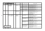
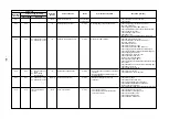
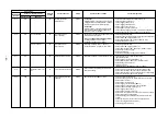
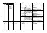
.): See attached table (p.95)
c) Push
SET
button. (OK if the display goes on.)
5
d) Using TEMP
/
buttons, enter
11
to the item code (DN).
e) Set the capacity by TIME
/
buttons.
f) Push
SET
button. (OK if the display goes on.)
Be sure to perform the following setting.
g) Using TEMP
/
buttons, enter
C8
to the item code (DN).
h) Set
0001
to the setting data by TIME
/
buttons.
i) Push
SET
button. (OK if the display goes on.)
j) Push
TEST
button to return the status to the normal stop status.
6
4) Next write the contents such as address setting, which were set at the local site after installation in EEPROM.
5) Using TEMP
/
buttons, specify
01
to the item code (DN). (Setup of filter sign lighting time)
6) In this time, compare the contents of the displayed setting data (p.95) with contents noted in
✻
✻
✻
✻
✻
1 (p.93) and the
customers’ information.
a) If data differs from them, change data to the noted contents by TIME
/
buttons and then push
SET
button. (OK if the display goes on.)
b) Do nothing if data matches with them.
7) Change the item code (DN) by TEMP
/
buttons. Check the contents of setting data as same as above
and then change data to noted data contents before exchange.
8) After then repeat procedures 6) and 7).
<EEPROM LAYOUT DIAGRAM>
EEPROM (IC10) is attached to IC socket. To remove it, use tweezers, etc.
To attach it, match the direction as shown in the figure.
∗
When replacing EEPROM,
be sure not to lead wire of IC.
6
5
3
2
4
1
ON / OFF
FAN
TEMP.
SWING/FIX
TIME
MODE
VENT
UNIT
SET
CL
FILTER
RESET TEST
TIMER SET
UNIT No.
SETTING
DATA
SET
R.C.
No.
9) After setting, push
TEST
button to return to the normal
stop status.
6
In a group operation, turn off the power supply once,
return group wiring between indoor air conditioners
and CN41 connector to the original status and then
turn on power supplies of all the indoor air condition-
ers. (Wait for approx. 1 minute until operation of the
remote controller.)
∗
The item code (DN) is
01
to
FF
. In the part of
the way, DN No. may skip. When you changed data
incorrectly and pushed
SET
button, you can return
data to one before change by pushing
CL
button if
item code (DN) is not yet changed.
Attach EEPROM so that notched direction of
IC socket matches with direction of EEPROM.
P.C. board (MCC-1403)
EEPROM (IC10)
IC socket
Notched
EEPROM
Notched
<Remote controller operation diagram>

