January 2000 © TOSHIBA TEC
1 - 61
FC-22 ADJUSTMENT
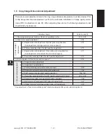
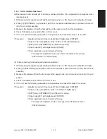
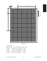
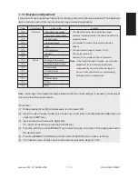
The following adjustments (c) to (i) should be conducted using Test Chart No. TCC-1. (Refer to page
1-64.)
(c) Primary-scanning reproduction ratio (Scanner)
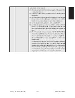
1. While pressing the digital keys [0] and [5] simultaneously, turn the power ON.
촞
(Adjustment mode)
2. Place Test Chart No. TCC-1 on the original glass (with the arrow positioned at the left rear side).
3. Press [ENERGY SAVER]
촞
[START] to make a copy in the mode of A4 (LT), 100%, full color and text/
photo.
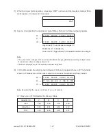
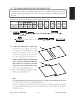
4. Measure the distance A between M1 and M2 on the copy with a ruler.
5. Check if the distance A is within a range of 200±0.5 mm or not.
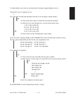
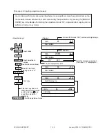
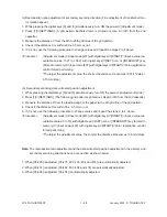
6. If it is not, change values using the following procedure, and repeat the steps 3. to 5. above.
<Procedure>
(Adjustment mode)
촞
(Input code [482] with digital keys)
촞
[START]
촞
(Input a value
(acceptable values : 0 to 255) with digital keys)
촞
[INTERRUPT] (Stored in memory)
(Input code [407] with digital keys)
촞
[START]
촞
Color registration control forced per-
forming
* The larger the adjustment value, the shorter the distance A becomes (0.2 mm/step).
(d) Scanner copy length reproduction ratio adjustment
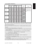
1. While pressing the digital keys [0] and [5] simultaneously, turn the power ON.
촞
(Adjustment mode)
2. Place Test Chart No. TCC-1 on the original glass (with the arrow positioned at the left rear side).
3. Press [ENERGY SAVER]
촞
[START] to make a copy in the mode of A4 (LT), 100%, full color and text/
photo.
4. Measure the distance B between M3 and M4 on the copy with a ruler.
5. Check if the distance B is within a range of 150±0.5 mm or not.
6. If it is not, change values using the following procedure, and repeat steps 3. to 5. above.
<Procedure>
(Adjustment mode)
촞
(Input code [104] with digital keys)
촞
[START]
촞
(Input a value
(acceptable values : 0 to 255) with digital keys)
촞
[INTERRUPT] (Stored in memory)
(Input code [407] with digital keys)
촞
[START]
촞
Color registration control forced per-
forming
* The larger the adjustment value, the longer the distance B becomes. (0.23 mm/step)
(e) CCD primary-scanning start position deviation
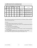
1. While pressing the digital keys [0] and [5] simultaneously, turn the power ON.
촞
(Adjustment mode)
2. Place Test Chart No. TCC-1 on the original glass (with the arrow positioned at the left rear side).
3. Press [ENERGY SAVER]
촞
[START] to make a copy in the mode of A4 (LT), 100%, full color and text/
photo.
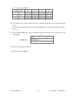
4. Measure the distance C from the left edge of the paper to the left-edge mark (5 mm) on the copy with
a ruler.
Содержание FC22
Страница 115: ...FC 22 PREVENTIVE MAINTENANCE 2 8 January 2000 TOSHIBA TEC Front side drive system 47 20 ...
Страница 121: ......
Страница 224: ...FC 22 FIRMWARE UPDATING 5 18 January 2000 TOSHIBA TEC Click Finish button then Virtual Modem installation is completed ...
Страница 235: ...January 2000 TOSHIBA TEC 5 29 FC 22 FIRMWARE UPDATING ...
Страница 237: ...FC 22 SERVICE HANDBOOK 6 WIRE HARNESS CONNECTION DIAGRAMS 6 2 DC Wire Harness ...
Страница 238: ...FC 22 WIREHARNESS CONNECTION DIAGRAMS 6 3 January 20000 TOSHIBA TEC ...

