FC-22 ADJUSTMENT
1 - 6
January 2000 © TOSHIBA TEC
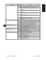
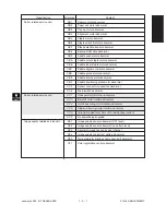
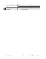
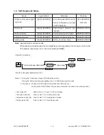
1. 2 Self Diagnostic Mode
Mode
Input method
Meaning
Clearing
Whole control panel light-
ing mode
Test mode
Test print mode
Adjustment mode
Setting mode
[0]+[1]+[POWER]
[0]+[3]+[POWER]
[0]+[4]+[POWER]
[0]+[5]+[POWER]
[0]+[8]+[POWER]
[C] or [POWER]
OFF/ON
[POWER] OFF/ON
[POWER] OFF/ON
[POWER] OFF/ON
[POWER] OFF/ON
All control-panel LEDs are lit,
and all LCD pixels are turned
on/off repeatedly.
Input/output signals are
checked
A test pattern print is made.
Adjustment of various items
Setting of various items
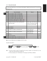
Note: Input method for various modes:
While pressing simultaneously the two digital keys corresponding to the mode you want to set
(for example, [0] and [5]), turn on the main switch [POWER].
0
1
CLEAR
CLEAR
POWER OFF/ON
(All control-panel LEDs light)
Power
(Check Key)
(Exit)
(Exit)
or
START
START
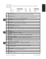
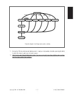
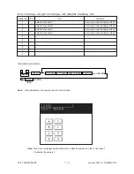
<Operation procedure>
• Whole control-panel lighting mode (01) :
Notes: 1. During the “Check keys” mode, [CLEAR] alone can do.
During the “Whole control-panel lighting mode”, [CLEAR] can clear the mode.
2. Check keys : Any key with LED (when it is pressed, the LED goes out.)
Any key without LED (When it is pressed, an indication is made in the message area.)
• Test mode (03)
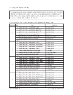
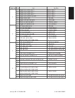
:Refer to Sec. 1.2.1 and 1.2.2 for test modes.
• Test print mode (04)
: Refer to Sec. 1.2.3 for test print modes.
• Adjustment mode (05) : Refer to Sec. 1.2.4 for adjustment modes.
• Setting mode (08)
: Refer to Sec. 1.2.5 for setting modes.
Содержание FC22
Страница 115: ...FC 22 PREVENTIVE MAINTENANCE 2 8 January 2000 TOSHIBA TEC Front side drive system 47 20 ...
Страница 121: ......
Страница 224: ...FC 22 FIRMWARE UPDATING 5 18 January 2000 TOSHIBA TEC Click Finish button then Virtual Modem installation is completed ...
Страница 235: ...January 2000 TOSHIBA TEC 5 29 FC 22 FIRMWARE UPDATING ...
Страница 237: ...FC 22 SERVICE HANDBOOK 6 WIRE HARNESS CONNECTION DIAGRAMS 6 2 DC Wire Harness ...
Страница 238: ...FC 22 WIREHARNESS CONNECTION DIAGRAMS 6 3 January 20000 TOSHIBA TEC ...


