Note:
Ensure this is done for each lever.
5.
Move the motion-control levers inward to the neutral
position and turn the ignition key to the Run position.
Note:
Do not start the machine.
Note:
The machine is now able to be pushed by hand.
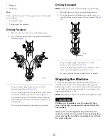
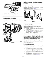
g017303
1 2
3
Figure 24
1.
Bypass-lever locations
3.
Lever position for pushing
the machine
2.
Lever position for
operating the machine
6.
When finished, ensure that the key has been returned to
the Stop position to avoid draining the battery charge.
Note:
If the machine fails to move, the electric brake may
still be engaged. If necessary, the electric brake can be released
manually; refer to
Releasing the Electric Brake (page 41)
.
Operating the Machine
Move the bypass levers rearward through the key hole and
down to lock them in place as shown in
Note:
Ensure this is done for each lever.
Converting to Side Discharge
(for models with 107 cm
(42-inch) decks)
The mower deck and mower blades shipped with this machine
were designed for optimum mulching and side discharge
performance.
Removing the Discharge Cover for the
Side Discharge
1.
Park the machine on a level surface and disengage the
blade-control switch.
2.
Move the motion-control levers outward to park
position, stop the engine, remove the key, and wait for
all moving parts to stop before leaving the operating
position.
3.
Remove the 2 bolts and nuts that secure the discharge
cover to the mower (
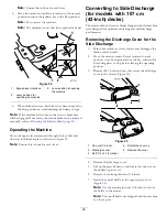
G009660
1
2
3
4
5
Figure 25
1.
Cap nut (1/4 inch)
4.
Rotate the cover up
2.
Discharge cover
5.
Remove the cover
3.
Bolt (1/4 x 2-1/2 inches)
4.
Remove the discharge cover.
5.
Lift up the grass deflector, and locate the lock nut on
the deflector pivot rod.
6.
Remove the existing thin nut (3/8 inch).
7.
Install the cutoff baffle to the exposed pivot rod
(
).
Note:
Use the existing thin nut (3/8 inch) to secure
the baffle to the mower.
Note:
The cutoff baffle was shipped with the machine
as a loose part.
26
Содержание timecutter zs 4200t
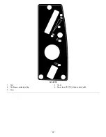
Страница 12: ...121 0772 1 Fast 4 Choke 2 Continuous variable setting 5 Power take off PTO blade control switch 3 Slow 12 ...
Страница 13: ...121 0773 1 Fast 4 Choke 2 Continuous variable setting 5 Power take off PTO blade control switch 3 Slow 13 ...
Страница 55: ...Schematics Electrical Diagram Rev A 55 ...
Страница 56: ...Notes 56 ...
Страница 57: ...Notes 57 ...
Страница 58: ...Notes 58 ...

