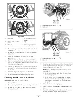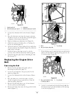
Figure 86
1.
Adjustment bolt
3.
Alternator
2.
Nut (alternator pivot point)
4.
Bolt (alternator pivot point)
2.
Loosen the adjustment bolt on the alternator (Figure
86).
3.
Move the alternator away from the engine to increase
the belt tension; move the alternator toward the engine
to decrease the belt tension (Figure 86).
4.
Tighten the alternator adjustment bolt (Figure 86).
5.
Check the tension of the belt; refer to Checking the
Tension of the Belt (page 59).
6.
If the belt tension is correct, tighten the nut and bolt at
the pivot point for the alternator (Figure 86); otherwise
repeat steps 2 through 5.
7.
Switch the battery disconnect switch to the On
position; refer to Battery-disconnect Switch (page 21).
8.
Install the right side panel; refer to Installing the Side
Panels (page 37).
Replacing the Engine Drive
Belt
Removing the Belt
1.
Remove the left and right side panels; refer to
Removing the Side Panels (page 36).
2.
Loosen the nut and bolt at the pivot point for the
alternator (Figure 86).
3.
Loosen the adjustment bolt on the alternator (Figure
86).
4.
Move the alternator toward the engine to loosen
the belt enough so that you can remove it from the
alternator pulley (Figure 86).
5.
Remove the belt from the grooves of the alternator,
the fan, and the crankshaft pulleys.
6.
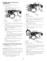
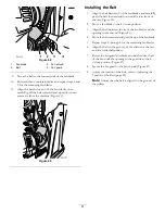
Remove the 4 bolts that secure the fan guard to the fan
shroud (Figure 87).
Figure 87
1.
Bolts
3.
Fan shroud
2.
Fan guard (mounting tab)
7.
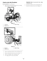
Rotate the fan guard counterclockwise around the drive
shaft of the fan until the opening in the guard is at the
4 o’clock position (Figure 88).
Figure 88
1.
Fan guard (rotated to the
4 o’clock position)
2.
Fan shroud
8.
At the 4 o’clock position of the fan shroud, align the
belt between the tip of the fan blade and the opening
in the shroud (Figure 89).
60
Содержание RT600
Страница 71: ...Notes 71...

