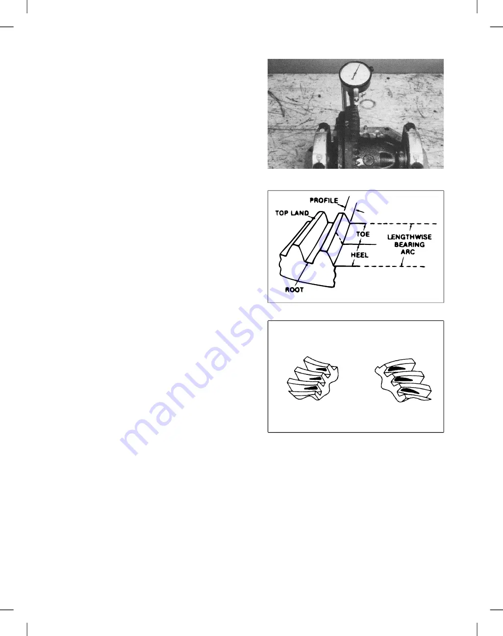
19. Using a dial indicator, check the ring gear backlash
in three equally spaced points. Ring gear backlash
should be .003 - .007 inch (.076 - .178 mm) and must
not vary more than .002 in. between points checked
(Fig. 53).
If the backlash is not in this range, move the shims which
are located beneath the differential bearings, from one
side to the other until the correct backlash is attained.
Checking Ring Gear Pattern
Figure 53
Final position of pinion is verified by using the gear
contact pattern method as described in the following
procedure.
Gear tooth Toe - the portion of the tooth surface at
the end towards the center.
Gear tooth Heel - the portion of the gear tooth at the
outer end.
Gear tooth Top Land - top surface of tooth.
Every gear has a characterisitc pattern. The illustrations
show typical patterns only and explaing how patterns
shift as gear location is changed. When making pinion
position changes, shims should be changed in the range
of .002 inch to .004 inch until a correct pattern has been
obtained.
When a change in backlash is required, backlash shims
should be changed in the range of 1-1/2 times the
amount of backlash required to bring the gears into
specification. For example, if the backlash needed to be
changed by .004 inch, the shim pack should be changed
by .006 inch as a starting point.
High backlash is corrected by moving the ring gear
closer to the pinion. Low backlash is corrected by
moving the ring gear away from the pinion. These
corrections are made by switching shims from one side
of the differential case to the other.
To check the ring gear and pinion pattern:
1. Paint the teeth of the ring gear, both drive and coast
side, with a gear marking compound, such as DyKem
Steel Blue.
2. While applying a light load to the ring gear, rotate the
pinion gear until the ring gear has made one complete
revolution. Study the patterns in the following illustra
tions and correct as necessary.
The preferred pattern is shown in Figure 54A. The drive
side pattern should be located at the toe portion of the
tooth. The coast pattern should also be at the toe portion
of the tooth.
Figure 54
Drive Side
Heel
Toe
Coast Side
Heel
Toe
Figure 54A
NOTE: When making changes, note that two variables
are involved. Example: If you have the backlash set
correctly to specifications and you change the pinion
position shim, you may have to readjust backlash to the
correct specification before checking the pattern.
Reelmaster
®
5100-D
Page 6 - 21 Rev. A
Repairs
Содержание Reelmaster 5100-D
Страница 2: ...This page is blank ...
Страница 4: ...This page is blank ...
Страница 8: ...Safety Instructions Page 1 4 Reelmaster 5100 D ...
Страница 12: ...Maintenance Interval Chart Maintenance Interval Chart Page 2 4 Rev A Reelmaster 5100 D ...
Страница 32: ...Troubleshooting Page 3 16 Reelmaster 223 D 5100 D ...
Страница 33: ...Reelmaster 223 D 5100 D Page 3 17 Troubleshooting ...
Страница 86: ...Specifications Page 4 2 2 Reelmaster 5100 D ...
Страница 90: ...Hydraulic Schematic Rev A Hydraulic Schematic Page 4 6 Reelmaster 5100 D ...
Страница 154: ...Logic Chart Page 5 2 Reelmaster 5100 D ...
Страница 155: ...Wiring Schematic S N Below 51001 Rev B Reelmaster 5100 D Page 5 3 Wiring Schematic ...
Страница 206: ...Repairs Page 5 48 Rev A Reelmaster 5100 D ...
Страница 230: ...Repairs Page 6 24 Reelmaster 5100 D ...
Страница 304: ...Repairs Page 8 22 Reelmaster 223 D 5100 D 5300 D ...
Страница 317: ...This page is blank ...
Страница 318: ...Commercial Products The Toro Company ...


