Cartridge Valve Service
1. Clean valve block to prevent contamination when
valve cartridge is removed.
2. Remove the cartridge valve from its port:
A. Remove nut from solenoid.
B. Remove solenoid coil and O-ring at each end of
solenoid coil.
C. Use a deep socket to remove solenoid cartridge
valve. NOTE: Use care when handling valve car
tridges because slight bending or distortion of stem
tube can cause binding and malfunction.
3. Visually inspect port in block for damage to sealing
areas, damaged threads or contamination.
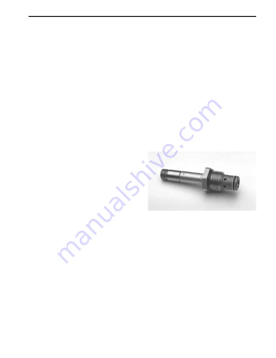
4. Visually inspect cartridge for damaged seals and
contamination (Fig. 78):
A. O-rings and back-up rings must be arranged
properly on the valve for proper operation. Replace
any damaged seals.
B. Contamination may cause valves to stick or hang
up. Contamination can become lodged in small valve
orifices or seat areas on poppet type valves causing
malfunction.
5. Clean and check for proper valve operation:
A. Use clean mineral spirits to clean cartridge valve.
Submerge the valve in clean mineral sprits and use
a probe to push the internal spool in and out 20 to
30 times to flush out contamination. Mineral spirits
does not affect the O-ring material. particles as fine
as talcom powder can affect the operation of high
pressure hydraulic valves.
Cartridge Installation
1. Lubricate all o-rings with clean hydraulic oil.
2. Carefully thread cartridge into the port by hand. Valve
cartridge should go in easily without binding.
3. Use a torque wrench and deep socket to tighten
cartridge valves to a torque of 35 ft-lb. Excessive torque
may cause the spool to bind and malfunction.
NOTE: Use care when handling solenoid valve car
tridges because slight bending or distortion of stem tube
can cause binding and malfunction.
4. Install solenoid coil. Make sure there is an O-ring at
each end of the coil. Apply “Loctite 242” or equivalent to
threads of stem tube before installing nut. Tighten nut
securing solenoid coil nut to a torque of 15 in-lb.
5. If problem still exists, remove valve again and replace
with a new valve.
Figure 78
Reelmaster
®
5100-D
Page 4 - 55 Rev. A
Mowing Circuit Repairs
Содержание Reelmaster 5100-D
Страница 2: ...This page is blank ...
Страница 4: ...This page is blank ...
Страница 8: ...Safety Instructions Page 1 4 Reelmaster 5100 D ...
Страница 12: ...Maintenance Interval Chart Maintenance Interval Chart Page 2 4 Rev A Reelmaster 5100 D ...
Страница 32: ...Troubleshooting Page 3 16 Reelmaster 223 D 5100 D ...
Страница 33: ...Reelmaster 223 D 5100 D Page 3 17 Troubleshooting ...
Страница 86: ...Specifications Page 4 2 2 Reelmaster 5100 D ...
Страница 90: ...Hydraulic Schematic Rev A Hydraulic Schematic Page 4 6 Reelmaster 5100 D ...
Страница 154: ...Logic Chart Page 5 2 Reelmaster 5100 D ...
Страница 155: ...Wiring Schematic S N Below 51001 Rev B Reelmaster 5100 D Page 5 3 Wiring Schematic ...
Страница 206: ...Repairs Page 5 48 Rev A Reelmaster 5100 D ...
Страница 230: ...Repairs Page 6 24 Reelmaster 5100 D ...
Страница 304: ...Repairs Page 8 22 Reelmaster 223 D 5100 D 5300 D ...
Страница 317: ...This page is blank ...
Страница 318: ...Commercial Products The Toro Company ...


