


4.
Unlatch the control-panel cover and move it aside
(
).
Figure 22
1.
Control panel
2.
Latch
5.
Locate and remove the 2 knockout plugs from the top
of the control panel (
Figure 23
1.
Knockout plugs
2.
Knockout plug locations
6.
Carefully cut and remove the decal material to expose
the control panel holes.
Note:
Remove only the knockout plugs and decal
material for the required switches.
7.
Deburr the newly exposed edges of the control panel.
8.
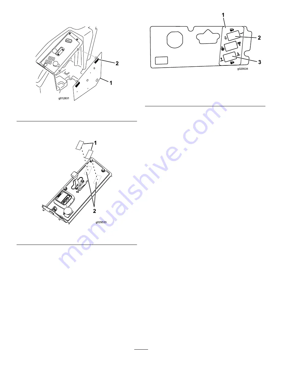
Clean the control panel surface and affix the decal
around the exposed holes (
).
Figure 24
1.
Decal
3.
Lift/lower switch
(3-position switch)
2.
Float/power-down switch
(2-position switch)
9.
Insert the switches into the appropriate mounting holes
(
).
Note:
Position the flat portion of the switch toward
the operator.
10