33
9. Secure trunnion to brake lever with washer and hair pin
cotter (Fig. 40).
10. Check the brake operation again; refer to Checking the
Brake, page 32.
Important
With the parking brake released, the rear
wheels must rotate freely when you push the mower. If
brake action and free wheel rotation cannot be achieved
contact your service dealer immediately.
3
6
4
m–6512
1
2
5
4
7
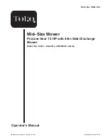
Figure 40
1.
Hairpin cotter and washer
2.
Trunnion
3.
Brake lever
4.
Wing nut
5.
Hole F
6.
Initial adjustment—
1–1/4 inch (32 mm)
7.
Rod
Adjusting the Electric Clutch
The clutch is adjustable to ensure proper engagement and
proper braking. Check adjustment after every 100 hours of
operation.
1. To adjust the clutch, tighten or loosen the lock nuts on
the flange studs (Fig. 41).
2. Check adjustment by inserting a feeler gauge thru the
slots next to the studs (Fig. 41).
3. The proper disengaged clearance between the clutch
plates is 0.012–0.024 inch (0.30-0.60 mm). It will be
necessary to check this clearance at each of the three
slots to ensure the plates are parallel to each other.
m–2600
1
2
3
Figure 41
1.
Adjusting nut
2.
Slot
3.
Feeler gauge
Servicing the Fuel Tank
Danger
In certain conditions, gasoline is extremely
flammable and highly explosive. A fire or
explosion from gasoline can burn you and others
and can damage property.
•
Drain gasoline from the fuel tank when the
engine is cold. Do this outdoors in an open area.
Wipe up any gasoline that spills.
•
Never smoke when draining gasoline, and stay
away from an open flame or where a spark may
ignite the gasoline fumes.
Draining the Fuel Tank
1. Park the machine on a level surface, to assure fuel tank
drains completely. Then disengage the power take off
(PTO), set the parking brake, and turn the ignition key
to off. Remove the key.
2. Close the fuel shut–off valve at the fuel tank (Fig. 42).
3. Squeeze the ends of the hose clamp together and slide it
up the fuel line away from fuel filter (Fig. 42).
4. Pull the fuel line off the fuel filter (Fig. 42). Open the
fuel shut-off valve and allow the gasoline to drain into a
gas can or drain pan.
Note: Now is the best time to install a new fuel filter
because the fuel tank is empty. Refer to Replacing the Fuel
Filter; page 34.
Содержание 30326
Страница 6: ...6...
Страница 8: ...8...
Страница 10: ...10 98 0776 98 3256 98 4387 1 Warning wear hearing protection 104 8186 104 8569 106 0699 106 5505 106 5532...