


15
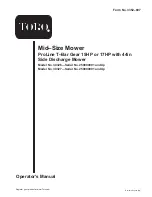
4. Secure the handle at each lower mounting hole with a
flange bolt (3/8 x 1 inch) and flange nut (Fig. 4).
Note: The handle position can be adjusted to match the
operator’s height preference.
1
2
3
4
8
7
5
6
m–6403
Figure 4
1.
Upper handle
2.
Rear frame
3.
Flange nut, 3/8 inch
4.
Flange bolt, 3/8 x 1 inch
5.
Upper mounting hole
6.
Lower mounting holes
7.
Low position
8.
High position
Note: Handle assembly must be installed before fuel tank is
installed.
Step
3
Installing the Fuel Tank
Parts needed for this step:
Qty.
Part
1
Fuel tank with studs installed
2
Bolt, 5/16 X 7/8 inch
2
Lock nut, 5/16 inch
4
Washer, 5/16 inch
1
Hose clamp
2
Lock washer, 5/16 inch
2
Spring
Procedure
1. Align fuel tank with the top of the rear frame (Fig. 5).
2. Secure the right side of the fuel tank to the rear frame
with 2 bolts (5/16 x 7/8 inch), lock washers (5/16 inch)
and washers (5/16 inch) (Fig. 5).
3. Secure the left side of the fuel tank to the rear frame
with 2 studs, washers (5/16 inch), springs and locknuts
(5/16 inch) (Fig. 5).
Note: Tighten left side of the fuel tank until it is completely
tight and then unscrew locknut one full turn. This will
allow the spring to work.
Содержание 30326
Страница 6: ...6...
Страница 8: ...8...
Страница 10: ...10 98 0776 98 3256 98 4387 1 Warning wear hearing protection 104 8186 104 8569 106 0699 106 5505 106 5532...


