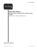
background image

Operator’s Manual

Original Instructions (EN)

Register your product at www.Toro.com

Form No. 3350–743

Mid–Size Mower

ProLine Gear 15 HP with 44in Side Discharge
Mower

Model No. 30437—Serial No. 240000001 and Up

Summary of Contents for ProLine 30437

Page 1: ...perator s Manual Original Instructions EN Register your product at www Toro com Form No 3350 743 Mid Size Mower ProLine Gear 15 HP with 44in Side Discharge Mower Model No 30437 Serial No 240000001 and Up ...

Page 2: ...g the Shipping Bracket 14 Installing the Handle Assembly 14 Installing the Fuel Tank 15 Checking and Adjusting the Shift Lever Plate 16 Installing the Control Rods 17 Page Installing the Hairpin Cotter Pins and Spacers 18 Operation 19 Think Safety First 19 Controls 19 Parking Brake and Neutral Lock 20 Starting and Stopping the Engine 20 Operating Mower Blade Control PTO 21 The Safety Interlock Sys...

Page 3: ...tion and Note emphasizes general information worthy of special attention Safety Note The addition of attachments made by other manufacturers that do not meet American National Standards Institute certification will cause noncompliance of this machine Improper use or maintenance by the operator or owner can result in injury To reduce the potential for injury comply with these safety instructions an...

Page 4: ...ake necessary repairs before resuming operations Keep hands and feet away from the cutting unit Look behind and down before backing up to be sure of a clear path Keep pets and bystanders away Slow down and use caution when making turns and crossing roads and sidewalks Stop blades if not mowing Be aware of the mower discharge direction and do not point it at anyone Do not operate the mower under th...

Page 5: ...bstacles such as rocks tree limbs etc from the mowing area Watch for holes ruts or bumps Tall grass can hide obstacles Use caution near drop offs ditches or embankments The machine could suddenly turn over if a wheel goes over the edge of a cliff or ditch or if an edge caves in Use extra care with grass catchers or other attachments These can change the stability of the machine Keep all movement o...

Page 6: ...6 ...

Page 7: ...7 Slope Chart Fold along appropriate line Align this edge with a vertical surface Tree Building Fence post pole etc Example Compare slope with folded edge ...

Page 8: ...8 ...

Page 9: ...ecals Safety decals and instructions are easily visible to the operator and are located near any area of potential danger Replace any decal that is damaged or lost 43 8480 66 1340 67 5360 68 8340 93 1122 95 2814 98 0776 98 3256 ...

Page 10: ...10 98 4387 1 Warning wear hearing protection 104 8186 104 8569 105 4111 105 4146 106 5532 106 0699 106 5511 ...

Page 11: ...rown objects 3 Do not operate the mower with the deflector up or removed 4 Stop the engine and pick up debris before operating 5 Cutting of hand or foot mower 6 Engine stop 7 Engine run 8 Hour meter 9 To park move the controls as illustrated 10 To drive move the controls as illustrated 11 To place the machine in neutral move the controls as illustrated 12 Power take off PTO ...

Page 12: ...ot possible then refuel such equipment on a truck or trailer from a portable container rather than from a gasoline dispenser nozzle If a gasoline dispenser nozzle must be used keep the nozzle in contact with the rim of the fuel tank or container opening at all times until fueling is complete Gasoline is harmful or fatal if swallowed Long term exposure to vapors can cause serious injury and illness...

Page 13: ...olt 5 16 x 7 8 inch Lock washer 5 16 inch Washer 5 16 inch Spring Hose clamp 1 2 2 2 4 2 1 Installing the fuel tank 4 No parts needed Checking and adjusting the shift lever 5 Clevis pin Washer Hairpin cotter pin 2 2 2 Installing the control rods 6 Hairpin cotter pin Spacers 2 6 Installing the hairpin cotter pins and spacers 7 Oil drain hose 1 Use for draining the engine oil 8 Operator s Manual Eng...

Page 14: ... nut Fig 3 1 2 3 4 4 m 7678 5 Figure 3 1 Center Gage Wheels and Spacer 2 Nut 3 Bolt 4 Washer Step 2 Installing the Handle Assembly Parts needed for this step Qty Part 1 Handle assembly 4 Bolt 5 16 X 7 8 inch 4 Lock nut 5 16 inch 1 Align handle with upper mounting holes in rear frame Fig 4 2 Secure the handle at each upper mounting hole with a flange bolt 3 8 x 1 inch and flange nut Fig 4 3 Select ...

Page 15: ... X 7 8 inch 2 Lock nut 5 16 inch 4 Washer 5 16 inch 1 Hose clamp 2 Lock washer 5 16 inch 2 Spring Procedure 1 Align fuel tank with the top of the rear frame Fig 5 2 Secure the right side of the fuel tank to the rear frame with 2 bolts 5 16 x 7 8 inch lock washers 5 16 inch and washers 5 16 inch Fig 5 3 Secure the left side of the fuel tank to the rear frame with 2 studs washers 5 16 inch springs a...

Page 16: ...fter lever plate The clearance between top and bottom of the shift lever should be equal Fig 8 2 If clearance is not correct remove lever and bend it slightly to adjust Fig 8 1 2 6 5 4 3 m 7679 Figure 7 1 Shift lever 2 Shift lever plate 3 Rubber seal washer 4 Square hole washer 5 Spring washer 6 Locknut 3 8 inch Note Do not bend lever while attached to transmission shaft or damage may occur 3 Shif...

Page 17: ...locks and into the clevis pins Fig 10 5 6 1 m 7669 4 2 3 Figure 10 1 Control rod 2 Drive lever 3 Hairpin cotter 4 Clevis pin 5 Handle 6 Neutral parking brake lock 4 Loosen the turn buckle wing nut Fig 11 3 1 m 6592 2 Figure 11 1 Turnbuckle 2 Wing nut 3 Control rod 5 Adjust the control rod length by rotating the turnbuckle until there is 3 16 to 1 4 inch 5 to 6mm clearance between the control rod e...

Page 18: ...in cotter Note Make sure there is at least one spacer used on each height of cut post 1 Remove the existing rear hairpin cotter pins from the rear height of cut posts 2 Install a spacer onto both rear height of cut posts and install the hairpin cotter pins 3 2 1 m 7584 Figure 13 1 Hairpin cotter 2 Spacer 3 Height of cut post rear shown 3 On the opposite side of the muffler install unused spacers o...

Page 19: ...e Off Switch PTO This pull switch is used in conjunction with the blade control bail to engage the clutch to drive the mower blades Gear Shift Lever Transmission has five forward speeds neutral and reverse and has an in line shift pattern Important Do not shift while unit is moving as transmission damage may occur Drive levers Shift to desired gear and release drive levers to engage traction opera...

Page 20: ...king brake lock 3 Park position 4 Drive lever 5 Full speed forward position 6 Grip Releasing the Neutral Lock 1 Squeeze the drive levers back to the grip 2 Place thumbs on the upper part of of locks and rotate them forward until in forward speed slot Starting and Stopping the Engine Starting 1 Make sure spark plug wire s are installed on spark plug s and fuel valve is open 2 Move the shift lever t...

Page 21: ...ol OPC levers against handle grip 3 Repeat procedure to engage mower blades if OPC levers are released 3 2 1 m 6581 Figure 20 1 Handle 2 Operator Presence Control levers OPC 3 Power take off switch PTO Disengaging the Mower Blades PTO 1 Release Operator Presence Control OPC levers to disengage blades Fig 20 This will also kill the engine The Safety Interlock System If safety interlock switches are...

Page 22: ...iately Driving Forward or Backward The throttle control regulates the engine speed as measured in rpm revolutions per minute Place the throttle control in the Fast position for best performance Driving Forward 1 To go forward move the shift lever to a forward gear 2 Release the parking brake refer to Releasing the Parking Brake page 20 3 Slowly release the drive levers to move forward Fig 21 To go...

Page 23: ...r damaged replace it immediately Never put your hands or feet under the mower Never try to clear discharge area or mower blades unless you release the bail and the power take off PTO is off Rotate the ignition key to Off Also remove the key and pull the wire off the spark plug s Adjusting the Height of Cut The height of cut can be adjusted from 1 to 4 1 2 inch 25 to 114 mm in 1 4 inch 6 mm increme...

Page 24: ... match the operator s height preference 1 Remove hairpin cotter washer and clevis pin securing control rod fitting to idler bracket Fig 25 m 6591 1 2 4 3 5 6 7 8 Figure 25 1 Upper handle 2 Rear frame 3 Flange nut 3 8 inch 4 Flange bolt 3 8 x 1 inch 5 Upper mounting hole 6 Lower mounting holes 7 Low position 8 High position 2 Loosen the upper flange bolts 3 8 x 1 inch and flange nut securing handle...

Page 25: ...k Electric Clutch adjust Engine clean outside 200 Hours Fuel Filter replace Engine Oil Filter change 200 hours or every other oil change Paper Air Cleaner replace 250 Hours Transmission Couplings grease1 400 Hours Wheel Bearings grease1 At storage or 400 Hours Chipped Surfaces paint Perform all maintenance procedures listed above before storage 1More often in dusty dirty conditions Important Refer...

Page 26: ...mage Fig 26 4 Unscrew the cover knob and remove the air cleaner cover Fig 26 5 Unscrew the 2 wing nuts and remove the air cleaner assembly Fig 26 6 Carefully pull the foam element off the paper element Fig 26 m 7452 2 3 4 5 1 6 Figure 26 1 Engine 2 Cover 3 Wing nut 4 Foam element 5 Paper element 6 Cover knob Cleaning the Foam Element 1 Wash the foam element in liquid soap and warm water When the e...

Page 27: ... parts to stop before leaving the operating position 4 Clean around the oil dipstick Fig 27 so that dirt cannot fall into the filler hole and damage the engine m 7449 2 1 Figure 27 1 Oil dipstick 2 Filler tube 5 Unscrew the oil dipstick and wipe the end clean Fig 27 6 Slide the oil dipstick fully into the filler tube but do not thread onto tube Fig 27 7 Pull the dipstick out and look at the end If...

Page 28: ...ter clockwise until the rubber gasket contacts the filter adapter then tighten the filter an additional 3 4 turn Fig 30 5 Fill the crankcase with the proper type of new oil refer to Servicing the Engine Oil page 27 6 Run the engine for about 3 minutes stop the engine and check for oil leaks around the oil filter 7 Check the engine oil level and add oil if needed Servicing the Spark Plugs Service I...

Page 29: ...ark Plugs 1 Install the spark plugs and the metal washer Ensure that the air gap is set correctly 2 Tighten the spark plugs to 16 ft lb 22 N m 3 Connect the wires to the spark plugs Fig 31 Cleaning the Cooling System Clean the air intake screen from grass and debris before each use Check and clean cooling fins and engine shrouds every 100 hours or yearly which ever comes first 1 Disengage the PTO ...

Page 30: ... the front wheel bearings and front spindles Fig 35 2 Raise the rear of the machine and use jack stands to support the machine 3 Remove the rear wheel and tire assembly 4 Remove rear wheel grease cap Lubricate the rear wheel bearing Fig 35 5 Install the grease cap 6 Install the rear wheel and tire assembly Note Make sure the rear wheel grease caps are removed before lubricating rear wheels m 6367 ...

Page 31: ... a fuse It requires no maintenance If the fuse blows check component or circuit for malfunction or short To replace fuse pull out on the fuse Fig 39 and push in new fuse 1 m 7676 Figure 39 1 Fuse 10 amp blade type Adjusting the Electric Clutch The clutch is adjustable to ensure proper engagement and proper braking Check adjustment after every 100 hours of operation 1 To adjust the clutch tighten o...

Page 32: ...llow the gasoline to drain into a gas can or drain pan Note Now is the best time to install a new fuel filter because the fuel tank is empty Refer to Replacing the Fuel Filter page 32 5 Install the fuel line onto the fuel filter Slide the hose clamp close to the valve to secure the fuel line 2 1 m 5235 Figure 41 1 Fuel shut off valve 2 Clamp Servicing the Fuel Filter Service Interval Specification...

Page 33: ...osition D Most severe belt wear 5 Spring 6 Adjustment bolt In position A Servicing the Brakes Service Interval Specification Before each use check brakes on both a level surface and slope Always set the parking brake when you stop the machine or leave it unattended If the parking brake does not hold securely an adjustment is required Checking the Brake 1 Park the machine on a level surface disenga...

Page 34: ... the trunnion into the hole for the brake rod Fig 44 Tighten the wing nut 9 Secure trunnion to brake lever with washer and hair pin cotter Fig 44 10 Check the brake operation again refer to Checking the Brake page 33 Important With the parking brake released the rear wheels must rotate freely when you push the mower If brake action and free wheel rotation cannot be achieved contact your service de...

Page 35: ...ade control bail and set the parking brake Turn the ignition key to off Remove the key and disconnect the spark plug wire s from the spark plug s Inspecting the Blades 1 Inspect the cutting edges Fig 46 If the edges are not sharp or have nicks remove and sharpen the blades Refer to Sharpening the Blades on page 36 2 Inspect the blades especially the curved area Fig 46 If you notice any damage wear...

Page 36: ... m 5199 6 Figure 49 1 Sail Area of Blade 2 Blade 3 Blade spindle 4 Washer 5 Blade bolt 6 Lock washer Sharpening the Blades 1 Use a file to sharpen the cutting edge at both ends of the blade Fig 50 Maintain the original angle The blade retains its balance if the same amount of material is removed from both cutting edges 1 m 1854 Figure 50 1 Sharpen at original angle 2 Check the balance of the blade...

Page 37: ... be 1 5 16 inch 33 mm plus or minus a 1 4 inch 6 mm 5 If the height at location A is not correct adjustment is needed 6 Loosen the carrier frame mounting bolts on both sides of the machine Fig 52 7 Align the carrier frame and engine deck to match 1 5 16 inch 33 mm plus or minus a 1 4 inch 6 mm at location A Fig 52 8 Tighten the carrier frame mounting bolts on both sides of the machine 1 A 3 5 4 2 ...

Page 38: ...nd set the parking brake 2 Stop the engine remove the key and wait for all moving parts to stop before leaving the operating position 3 Adjust the tire pressure in all tires to specifications on page 31 4 Measure carrier frame height at location A Fig 55 5 Measure carrier frame height at location B Fig 55 6 If the carrier frame height is not the same move spacers from top or bottom of caster wheel...

Page 39: ...utting edge of the blades Fig 57 5 Check the side to side leveling of the cutting unit 6 Tighten the jam nuts Fig 58 Checking the Deck Side to Side Leveling 1 Check the tire pressure on both deck and traction unit 2 Position the blades side to side Fig 59 Measure at A and B locations Fig 59 from a level surface to the cutting edge of blade tips Fig 60 3 The difference between measurements A and B ...

Page 40: ...o allow the belt to be removed and remove the belt 4 Install a new belt 5 Install the top capscrew securing the idler support and idler bracket to the rear frame Fig 63 6 Tighten the bottom two mounting screws enough to allow the belt to pass between the drive pulley and idler support Fig 63 2 1 4 3 5 m 6597 Figure 63 1 Top capscrew 2 Idler bracket 3 Idler support 4 Bottom capscrew 5 Traction driv...

Page 41: ...tall the deck covers onto the cutting unit then reinstall and tighten the knobs 11 Install the carrier frame cover onto the cutting unit then install and tighten the hand knobs 4 3 1 5 3 2 6 m 6529 Figure 65 1 Deck belt 2 Idler arm spring 3 Outside pulley 4 PTO drive Belt 5 Center Spindle Pulley 6 Deck belt guide Replacing the PTO Drive Belt Squealing when the belt is rotating blades slipping when...

Page 42: ...rrect installation and to maintain a level deck 4 2 1 3 2 m 6372 Figure 67 1 Locking Pin 2 Spacers locate as required 3 Carrier frame mounting tube 4 Caster wheel fork 4 Insert a pin punch into the mounting tube and carefully drive out the bushings Fig 68 Clean the inside of the mounting tube 5 Grease the inside and outside of the new bushings Use a hammer and flat plate to carefully drive the bus...

Page 43: ...wheel bolt and locknut Tighten the locknut until the spanner bushing bottoms against the inside of the caster forks Fig 69 7 Grease the fitting on the caster wheel Replacing the Grass Deflector An uncovered discharge opening could allow the lawn mower to throw objects in the operator s or bystander s direction and result in serious injury Also contact with the blade could occur Never operate the l...

Page 44: ... Neutral W PK Y BU Y GND 10A F1 BU BN BK RED PINK Y BK BK 1 2 5 4 7 8 PK TAN PK Y GREY W GREEN VIO K1 Interlock Relay Clutch PTO Switch Off Pistol Grip M S KAW Gear KEY SWITCH ORANGE T BROWN WIRE COLOR CODES BLACK R PK 2 3 5 4 1 HR MTR OPTIONAL OPEN ON CLOSED OFF BLUE AC AC SPARK PLUG RECTIFIER MAG DC IGNITION MODULES SPARK PLUG ...

Page 45: ...tabilizer conditioned gasoline over 90 days 9 Remove the spark plug s and check its condition refer to Servicing the Spark Plug Service page 28 With the spark plug s removed from the engine pour two tablespoons of engine oil into the spark plug hole Now use the starter to crank the engine and distribute the oil inside the cylinder Install the spark plug s Do not install the wire on the spark plug ...

Page 46: ...low 2 Add oil to crankcase 3 Cooling fins and air passages under engine blower housing are plugged 3 Remove obstruction from cooling fins and air passages Machine does not drive 1 Shift lever is in NEUTRAL 1 Move shift lever to a drive gear position 2 Traction belt is worn loose or broken 2 Change Belt 3 Traction belt is off pulley 3 Change Belt 4 Broken or missing idler spring 4 Replace spring 5 ...

Page 47: ...ect 5 Adjust tire pressure 6 Blade spindle bent 6 Contact Authorized Service Dealer Blades do not rotate 1 PTO Drive belt is worn loose or broken 1 Install new drive belt 2 PTO Drive belt is off pulley 2 Install drive belt and check adjusting shafts and belt guides for correct position 3 Deck belt is worn loose or broken 3 Install new deck belt 4 Deck belt is off pulley 4 Install deck pulley and c...

Page 48: ...vered There is no other express warranty except for special emission system coverage on some products This express warranty does not cover the following Cost of regular maintenance service or parts such as filters fuel lubricants tune up parts blade sharpening brake and clutch adjustments Any product or part which has been altered or misused or required replacement or repair due to normal wear acc...

Reviews: