34
Important
The following procedures apply when
servicing a (dry) battery that has replaced the original
battery. The original (wet) battery does not require
service.
Check the electrolyte level in the battery every 100 hours.
Always keep the battery clean and fully charged. Use a
paper towel to clean the battery case. If the battery
terminals are corroded, clean them with a solution of four
parts water and one part baking soda. Apply a light
coating of grease to the battery terminals to reduce
corrosion.
Voltage: 12 v, 450 Cold Cranking Amps
Checking the Electrolyte Level
1.
Open covers to see into the cells. The electrolyte must
be up to the lower part of the tube (Fig. 64).
Important
Do not allow the electrolyte to get below
the plates. (Fig. 64).
1
2
3
1262
Figure 64
1. Filler caps
2. Lower part of tube
3. Plates
2.
If the electrolyte is low, add the required amount of
distilled water; refer to Adding Water to the Battery,
below.
Adding Water to the Battery
The best time to add distilled water to the battery is just
before you operate the traction unit. This lets the water
mix thoroughly with the electrolyte solution.
1.
Clean the top of the battery with a paper towel.
2.
Lift off the filler caps (Fig. 64).
3.
Slowly pour distilled water into each battery cell until
the level is up to the lower part of the tube (Fig. 64).
Important
Do not overfill the battery because
electrolyte (sulfuric acid) can cause severe corrosion and
damage to the chassis.
4.
Press the filler caps onto the battery.
Charging the Battery
Important
Always keep the battery fully charged
(1.260 specific gravity). This is especially important to
prevent battery damage when the temperature is below
32
°
F (0
°
C).
1.
Check the electrolyte level; refer to Checking
Electrolyte Level, page 34.
2.
Remove the filler caps from the battery and connect a
battery charger to the battery posts (Fig. 2). Charge the
battery at a rate of 6 to 10 amperes for a minimum of
1 hour (12 volts).
3.
Install the filler caps after the battery is fully charged.
Charging the battery produces gasses that can
explode.
Never smoke near the battery and keep sparks
and flames away from battery.
Warning
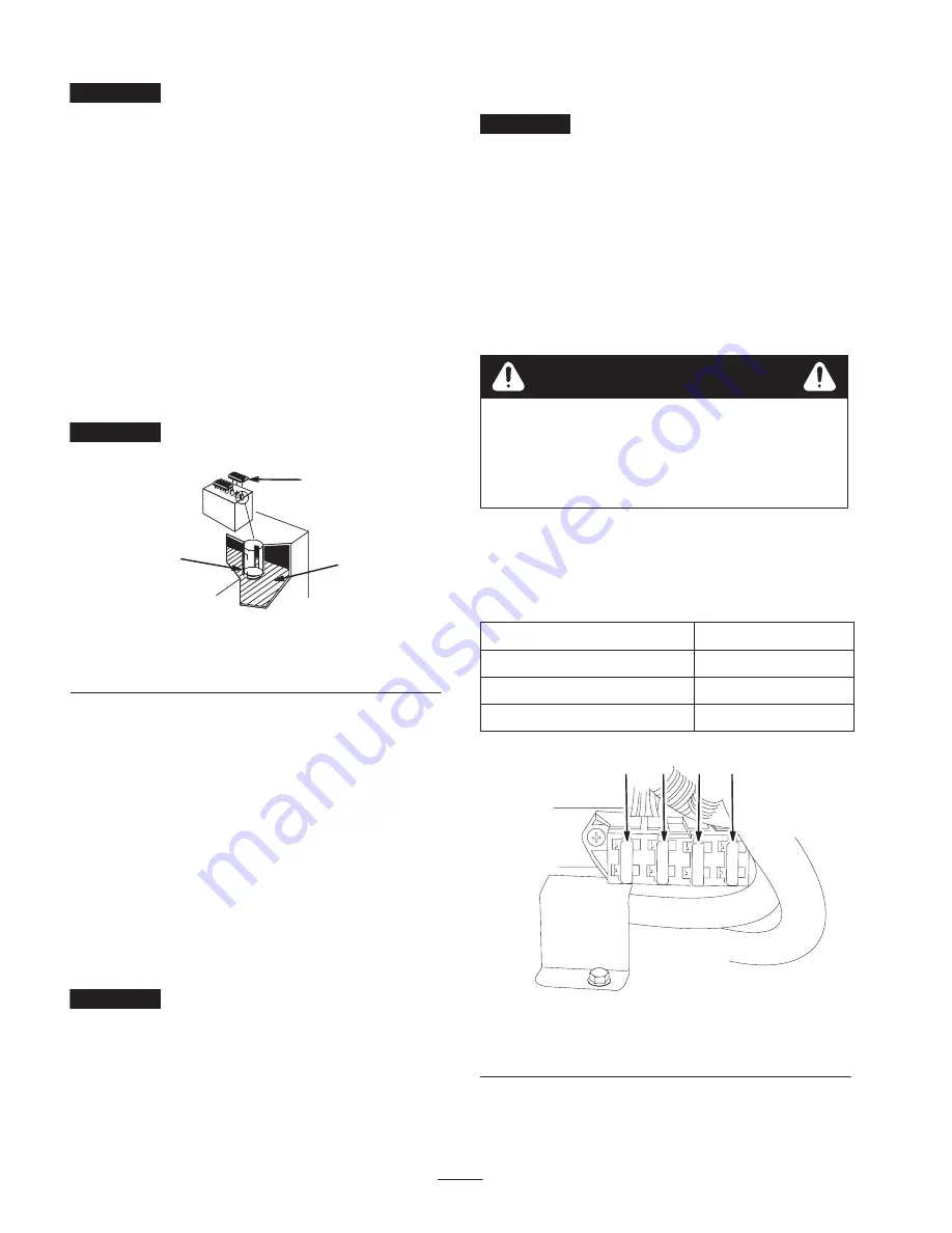
Replacing the Fuses
There are 4 fuses in the electrical system. They are
located inside the rear access cover (Fig. 65).
Start Circuit
30 amp.
Charge Circuit
25 amp.
Interlock Circuit
10 amp.
Headlight (optional)
10 amp.
1
2
3
4
m–7524
Figure 65
1. Start circuit
2. Charge circuit
3. Headlight
4. Interlock circuit
Содержание 22308
Страница 6: ...6 Slope Chart Note This page may be copied for personal use only M 4402...
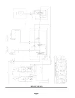
Страница 37: ...37 Schematics Electrical Schematic...
Страница 38: ...38 Hydraulic Schematic...


