12
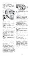
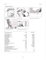
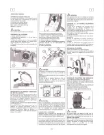
Note: The wheels of the squeegee support
must be adjusted through the registers (5)
at the same height so that the squeegee
works parallel to the floor.
ADJUSTMENT OF THE SQUEEGEE
INCLINATION
In case of need, to increase the rubber
bending in the central part, it is necessary
to tilt the squeegee rotating counterclock-
wise the register (6). To increase the rub-
ber bending on the squeegee extremities,
rotate the register clockwise.
SPLASH GUARD ASSEMBLY
The two splash guards have to be as-
sembled onto the brushes base group.
Insert the metal strips inside the suitable
slots present on the rubber. Place the
round hole at the flat extremity of the strip
onto the screw placed in the front part of
the brushes base group. Secure the strips
through the nut blocking it.
Hook the spring in the rear part of the
brushes base group to the slot placed at the
extremity of the metal strip still free.
Please act as above for both the splash
guard rubbers, paying attention to reduce
to the minimum the gap between the two
rubbers in the front part of the brushes
base group.
With brushes assembled, the splash guard
must slightly touch the floor.
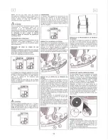
BRUSH ASSEMBLY
1. Switch off the machine acting upon
the general switch (12). For machines
equipped with key switch (see under "OP-
TIONAL ACCESSORIES"), turn the key
counterclockwise.
2. Acting upon the pedal (10) lift the brush
base group.
3. With the brush base group in lifted
position, insert the brush into its plate seat
underneath the brush base turning it until
the three metal buttons are properly seated
in their slots; turning them until the three
metal buttons are properly seated.
The figure shows the rotating sense for the
brush coupling of the BD 20/11T.
ATTENTION
:
Use only brushes supplied with the ma-
chine or the ones indicated in the para-
graph “RECOMMENDED BRUSHES”.
The use of other brushes can compromise
the security.
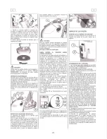
RECOVERY TANK
Check that the cover of the suction filter
(1) is correctly secured, after rotating the
levers and that the suction motor hose (2)
is correctly connected.
Verify also that the squeegee hose is cor-
rectly inserted into the seats (3 and 4) and
that the exhaust hose plug (5) placed in the
front part of the machine, is closed.
DETERGENT SOLUTION TANK
The capacity of the detergent solution tank
is indicated in the technical data.
Open the screw plug (1) placed in the
rear left part of the machine and fill the
detergent solution tank with clean water at
a maximum temperature of 122°F (50°C).
Add the liquid detergent in the percentage
and conditions foreseen by the manufac-
turer. To avoid excessive foam, which
could cause problems to the suction motor,
use the minimum percentage of detergent.
Screw down the plug to close the tank.
ATTENTION:
Use always low foam detergent. To avoid
foam presence, before starting working
operation, introduce into the recovery tank
a minimum quantity of anti-foam product.
Never use pure acid.


