background image

SERVICE  MANUAL

R.P.S. Corporation   

Phone:  

1-800-634-4060

P.O. Box 241  


Fax:   

1-866-632-6961

Racine, Wisconsin 


Version 1.0

 2023 SERIES

Содержание 2023 Series

Страница 1: ...SERVICE MANUAL R P S Corporation Phone 1 800 634 4060 P O Box 241 Fax 1 866 632 6961 Racine Wisconsin Version 1 0 2023 SERIES ...

Страница 2: ...he purpose Accordingly anyone who intends to use a replacement part service procedure or tool which is not recommended by the equipment manufacturer must determine that neither his safety nor the safe operation of the equipment will be jeopardized by the replacement part service procedure or tool selected It is important to note that this manual contains various cautions and notices that must be c...

Страница 3: ...When properly used it will meet the needs of technicians and equipment owners No part of this publication may be reproduced stored in any retrieval system or transmit ted on any form or by any means including but not limited to electronic mechanical pho tocopying recording or otherwise with out the prior written permission of the Mid Central Corporation This includes all text illustrations tables ...

Страница 4: ... only and in an indoor environment with the recommended pads and brushes with ap proved cleaning solutions DO NOT OPERATE THE UNIT UNLESS TRAINED AND AUTHORIZED UNLESS OPERATOR MANUAL IS READ AND UNDERSTOOD IF UNIT IS NOT IN PROPER OPERATING CONDITION WHEN OPERATING UNIT WEAR PROPER PROTECTIVE EQUIPMENT REMOVE LOOSE OBJECTS FROM THE FLOOR THAT MAY BE PROJECTED FROM THE REVOLVING BRUSHES DO NOT OPE...

Страница 5: ... straight up or down the ramp Never drive across the incline Do not back down or turn on ramps Always use the charger provided by the manufacturer to charge the machine It is an automatic charger specifically designed to charge at the appropriate rate If you must use a different charger disconnect the batteries from the machine as this will protect the on board electronics Understand the dynamic br...

Страница 6: ...BLANK THIS PAGE WAS INTENTIONALLY LEFT BLANK ...

Страница 7: ...H PRESSURE GAUGE 2 4 SQUEEGEE SYSTEM 3 1 SQUEEGEE SYSTEM COMPONENTS 3 1 SQUEEGEE SUSPENSION BREAKDOWN 3 2 TRIANGLE PLATE TOW BAR 3 3 UP DOWN MOVEMENT 3 3 SIDEWAYS MOVEMENT 3 3 SQUEEGEE BLADES 3 3 REPLACING BLADES 3 4 ORDERING BLADES 3 4 SQUEEGEE ADJUSTMENT 3 5 PITCH ADJUSTMENT KNOB 3 5 SQUEEGEE ADJUSTMENT EXAMPLES 3 6 SQUEEGEE LIFT SYSTEM 4 1 TO OPERATE 4 1 SQUEEGEE LIFT ADJUSTMENTS 4 1 RECOVERY S...

Страница 8: ...G BRUSHES 7 2 BRUSH LIFT SYSTEM 8 1 BRUSH LIFT ELECTRICAL CIRCUIT 8 1 ACTUATOR 8 1 DOWN PRESSURE 8 2 BRUSH LIFT SYSTEM ADJUSTMENTS 8 2 BRUSH LIFT ACTUATOR 8 2 ACTUATOR ADJUSTMENT 8 3 LINKAGE ADJUSTMENT 8 3 TRACTION DRIVE SYSTEM 9 1 CHASSIS SYSTEM 10 1 CHASSIS REPLACEMENT 10 1 BATTERIES 11 1 BATTERY SAFETY 11 1 DANGER OF EXPLODING BATTERIES 11 1 SAFE CHARGING 11 1 SAFETY PRECAUTIONS 11 1 HANDLING B...

Страница 9: ...ING 11 5 HYDROMETERS 11 5 FLOAT TYPE 11 5 DIAL TYPE 11 5 LOAD TESTING 11 7 BATTERY REPLACEMENT 11 8 BATTERY CHARGERS 11 8 ELECTRICAL SYSTEM 12 1 SWITCHES 12 1 RELAYS 12 1 MOTORS 12 1 ACTUATORS 12 1 WIRING 12 1 REPAIR INSTRUCTIONS RI 1 2023 01 SHROUD CURTAIN ADJUSTMENT RI 1 2033 02 SCRUB DECK ACTUATOR R R RI 2 2023 03 SOLUTION SOLENOID VALVE RI 8 2023 04 CIRCUIT BREAKER RESETABLE R R RI 13 2023 06 ...

Страница 10: ...2023 Service Manual V1 0 TOC toc 4 TABLE OF CONTENTS BLANK THIS PAGE WAS INTENTIONALLY LEFT BLANK ...

Страница 11: ...Rate 0 2 GPM 0 7 56 liters min Operating Noise Level at operator 70 dB A Forward Scrub Speed 0 300 ft min 4 1 2 mph 0 92 meters min 7 5 kph Vacuum Motor 3 Stage 75 hp 660 watt Water lift 68 Airflow 72 cfm Power Source Batteries 2023 Standard 2 12 Volt 140 amp hour capacity Weight Each 66 lbs 30 kg High Capacity 2 12 Volt 205 amp hour capacity Weight Each 122 lbs 56kg Battery Compartment Size Height...

Страница 12: ...ss Weight 458 lbs 458 lbs 484 lbs 208 kg 208 kg 220 kg Cleaning Width 20 in 20 in 23in 51 cm 51 cm 59 cm Cleaning Rate Per Hour 19 842 sq ft hour 19 842 sq ft hour 22 491 sq ft hour 1843 sq meters hour 1843 sq meters hour 2090 sq meters hour NET WEIGHT Standard equipped machine with no options installed Empty recovery and solution tanks and no batter ies pad holder or scrub brush GROSS WEIGHT Stan...

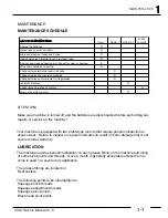
Страница 13: ...ure to inspect on regular intervals can result in motor damage that is not covered under warranty LUBRICATION The machine requires periodic lubrication on each grease fitting on the machine and oiling of some pivot points and threads Once a month is generally acceptable unless the ma chine is used in a severe duty application The grease fittings are located on Rear casters The following points to be...

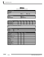
Страница 14: ...2023 Service Manual V1 0 1 1 2 MAINTENANCE ...

Страница 15: ...2023 Service Manual V1 0 1 1 3 MAINTENANCE ...

Страница 16: ...2023 Service Manual V1 0 1 1 4 MAINTENANCE BLANK THIS PAGE WAS INTENTIONALLY LEFT BLANK ...

Страница 17: ...RAIN 6 SQUEEGEE ASSEMBLY 7 FRONT WHEELS 8 REAR CASTERS 9 SOLUTION FILTER 10 SQUEEGEE LIFT 11 CHARGER PORT 12 RECOVERY DRAIN HOSE 1 2 3 4 5 6 8 20 13 14 15 7 13 SOLUTION TANK 14 BODY LOCK DOWN SCREW 15 BODY ALLEN WRENCH 16 DRAIN SAVER SCREEN 17 VACUUM FLOAT AND SCREEN 18 SOLUTION VALVE 19 SOLUTION FILL 20 BRUSH DRIVE ADJUSTER 12 9 10 11 16 17 18 19 ...

Страница 18: ...ted at the rear of the machine near the floor and has a high visibility yellow cover on it It was designed to be easily operated with a foot Battery Charger Port 11 The plug where you plug in the battery charger Recovery Tank 12 The recovery tank holds the dirty water that is removed from the floor by the squeegee The capacity of it is 33 gallons The tank additionally holds the float assembly that cl...

Страница 19: ...ion Switch D Brush Motor Switch E Handle Switch F Battery Gauge G Brush Pressure Gauge H Emergency Stop Optional I Key Switch Optional J Vacuum Motor Circuit Breaker K Brush Motor Circuit Breaker L Brush Actuator Circuit Breaker M Water Jet Switch Optional N Hour Meter O Serial Number Plate P Power Indicator P ...

Страница 20: ...he needle will travel Increasing your brush pressure can dramatically shorten the overall run time of the machine because of increased power consumption CONTROL SWITCHES Main Power Switch A Turn power on and off to the entire machine Vacuum Switch B Turns the vacuum motor on and off Solution Switch C When in the on position the solution flows when the brushes run Brush Motor Switch D When in the on...

Страница 21: ...on proper adjustment and main tenance The machines recovery system also has to be operating properly for the squee gee to perform well The squeegee tool with replaceable rollers wheels blades A suspension that mounts the squeegee to the machine and allows the squeegee to move up and down with variations in the floor and pivot in turns A lift system that allows the operator to raise the squeegee off...

Страница 22: ...oper spacing between the triangle plate and the trail Arm E SQUEEGEE TRIANGLE PLATE The squeegee is mounted to the triangle plate and ties it to the trail arm F SPRING Supplies pressure between the Triangle plate and the trail arm Helps hold the adjust ment The squeegee will not operate without this spring G PITCH ADJUSTMENT KNOB The knob used to pitch the squeegee frontward or backwards The squee...

Страница 23: ...as shown If the squeegee suspension does not move up and down properly check the bolts and the Oilite bushings at the pivot point If the bolts are too tight they may have been tightened by customer by mistake or the bushings are dried out or worn the squeegee will not be able to float properly SIDEWAYS MOVEMENT The squeegee must be allowed to move from side to side so that if it hits an obstacle it...

Страница 24: ...er on the top of the squeegee body and order the corresponding blade size 32 35 38 or 45 inches 2 Choose the appropriate material Gum rubber These blades are tan in color and best for most applications including irregular floors They wear out quickly on rough floors however and do not tolerate oil other petroleum products or heavy citrus cleaners The kit number suffix for gum rubber is G Example 28 7...

Страница 25: ...o achieve is to have the squeegee PERFECTLY parallel with the floor From that point pitch ing the squeegee forward about one half degree of pitch will reduce air leak Pitching the squeegee backwards about one half degree will increase the air leak PITCH ADJUSTMENT KNOB The triangular shaped plate that the squeegee bolts to is adjustable for a slight amount of up down pitch As you turn the knob the ...

Страница 26: ...2023 Service Manual V1 0 3 3 6 SQUEEGEE SYSTEM SQUEEGEE ADJUSTMENT EXAMPLES ...

Страница 27: ...queegee blade kit The trailing wheels should be changed when the blades are changed or immediately if they become damaged Our squeegee trailing wheel system is theoretically not adjustable meaning that it is not intended for end users to adjust it If you have good wheels of the correct diameter on the squeegee and they contact the floor incorrectly then observe the space between the wheels and a fla...

Страница 28: ...2023 Service Manual V1 0 3 3 8 SQUEEGEE SYSTEM ...

Страница 29: ...ace brackets if worn or bent Remove squeegee from machine ensure it has a good set of squeegee blades on it and set it on a flat surface NO YES Are both wheels the same distance from the ground Install or remove washers underneath squeegee trailing wheel brackets to correct NO NO YES NO NO Inspect squeegee tool and linkage to the machine for any bent parts YES Are there bent parts Install new part...

Страница 30: ... clearance on all machines except the 390 420 series It there proper clearance there Check cable clearance slack YES NO Is there proper clearance and slack Call the factory YES Does the machine operate properly Bill the customer Does the machine work properly Operate the machine and verify squeegee operation Adjust the clearance Adjust clearance and or slack Operate the machine and verify squeegee...

Страница 31: ... lower the squeegee place your foot under the yellow lever located at the right rear of the machine below the control panel To lift the squeegee press down on the yellow colored lever with your foot SQUEEGEE LIFT ADJUSTMENTS There are no provisions for adjustment of the squeegee lift If the squeegee is not raising and lowering properly it is due to bent or worn part or parts Inspect the lift assem...

Страница 32: ...2023 Service Manual V1 0 4 4 2 SQUEEGEE LIFT SYSTEM BLANK THIS PAGE WAS INTENTIONALLY LEFT BLANK ...

Страница 33: ...r and out through the vacuum motor The recovery tank is equipped with a clear lid that allows the operator to observe the conditions inside the recovery tank as well as the recovery water level inside Inside the recovery tank there are 4 major components The recovery lid drain saver vacuum float and the water baffle RECOVERY LID The recovery is made from 1 8 thick stainless steel with a clear dome T...

Страница 34: ...idity to the tank walls and lessens the sloshing of the water inside the recovery tank VACUUM FLOAT The vacuum float assembly is located inside the recovery tank and is accessed by opening the re covery tank lid The float stops the flow of air in the event that the recovery tank is filled to capacity DRAIN HOSE To drain the recovery system the machine is equipped with a poly hose with an integrated flo...

Страница 35: ...t ball cage clean YES Verify customer complaint Is there a problem YES Empty tank and clean Drain Saver and float ball cage NO Retest the machine Are the gaskets the clear recovery lid and the stainless recovery tank door in good condition YES Repair or replace parts as needed Retest machine Did this remedy the problem NO YES GOTO PAGE 2 Turn on vacuum switch YES NO NO Does the vacuum motor run Ve...

Страница 36: ...r on proper machine maintenance Check vacuum lift at the end of the squeegee hose NO YES YES NO Do you have good vacuum at the squeegee hose Call the factory YES NO Remove squeegee and see if it is clogged YES Is the squeegee adjusted properly Adjust squeegee and retest machine See squeegee section for assistance Did this remedy the problem NO NO FROM PAGE 1 Bill customer See Next Page MODEL 2023 ...

Страница 37: ...um Call the factory Unbolt the vacuum motor from the tank Test the vacuum directy at the vacuum motor Check the motor saver for cracks make sure all the gaskets are in good condition and check the duck bill Is everything is good order Call the factory Repair as necessary and then retest machine Did this remedy the problem Bill the customer YES NO YES NO YES NO Do you have good vacuum NO YES NO YES...

Страница 38: ...2023 Service Manual V1 0 5 5 6 RECOVERY SYSTEM BLANK THIS PAGE WAS INTENTIONALLY LEFT BLANK ...

Страница 39: ...solution to flow onto the top of the brush where it can run through the shower feed holes and onto the scrubbing surface On early models the solution solenoid valve has a knob and is adjustable to control the amount of solution that is dispensed onto the floor On later models the knob was removed from the solenoid and a ball valve was added to control the volume of solution dispensed DISPENSING SOLU...

Страница 40: ...R Drain solution tank with the drain hose Re move squeegee tool from the machine Lower the squeegee linkage Reach under the ma chine and unscrew and remove the clear part of the plastic filter housing Remove screen and clean Replace screen and clear part of filter housing DRAINING SOLUTION TANK Detach the solution drain sight gauge hose from the upper barb and lower into a suitable drain or receptac...

Страница 41: ...ater NO YES Is the solution screen clogged Solution tank outlet is clogged Clean out tank and remove foreign material from water outlet NO YES Clean solution screen and flush out the solution tank YES Is the water switch turned on Turn on the water switch NO YES NO NO Advise customer on proper machine operation YES See Next Page Is the ball valve at the brush deck open YES NO Open the ball valve S...

Страница 42: ...oes the scrub deck turn on when the green button is depressed YES See Brush drive system section NO Was the screw backed out all the way and secured with a locknut Back out all the way and install lock nut Retest machine NO Use your meter to check for continuity on the deltrol valve Was there resistance or an open circuit Call the factory Replace the deltrol valve Open circuit Resistance Replace t...

Страница 43: ...ropulsion The knob applies pressure to a wheel that runs on the top of the scrub brush or pad holder applying pressure to one side of the brush or pad holder causing the brush or holder to pull the machine forward BRUSH DRIVE ELECTRICAL CIRCUIT The negative side of the battery connects directly to the scrub brush motor The positive side of the battery passes through a relay from the relay to the 3...

Страница 44: ...BRUSHES Raise the brush deck as high as it will go with the brush deck switch Turn machine power off Loosen the two knobs at the front of the scrub deck and slide the shroud off the deck Rotate the brush until both tabs of the spring clip are ac cessible Squeeze the two tabs together and the brush will drop off To install a brush reverse the procedure SETTING BRUSH PRESSURE Lower the scrub deck to...

Страница 45: ...witch NO Is the battery gauge in the green zone Charge Batteries Is the actuator circuit breaker tripped Reset breaker and test for proper operation NO YES YES NO YES YES NO Press the green handle bar button while touching the side of the brush motor relay You should feel the relay click when you depress the button Does the relay click GO TO PAGE 2 A NO Check for and power at the brush motor when ...

Страница 46: ...re going to the coil circuit on the brush relay when the green handle bar button is depressed FROM PAGE 1 B Check for battery voltage on the black wire to the brush relay coil circuit Is there battery voltage Repair the wiring and retest the machine YES NO Replace the brush relay Retest the machine YES Repair the wiring from the buss to the brush motor relay NO Check for battery voltage on the oth...

Страница 47: ...DOWN PRESSURE SPRINGS ACTUATOR BRUSH LIFT ELECTRICAL CIRCUIT The negative side of the battery is connected to the brush deck lift switch Positive power from the main power switch is fed to the brush deck lift switch The switch is then wired to the brush deck actuator with a 2 amp circuit breaker in line on the positive side When the switch is depressed to lower the brush current is sent to the bru...

Страница 48: ...e adjustment that controls how high the brush deck will lift off the floor To access the actuator and its linkage the body of the machine must be tipped back To do this you must first drain the solution and recovery tanks completely Then use the Allen wrench located on the side of the scrub deck to remove the body hold down bolts Once the body hold down bolts have been removed you can then use the h...

Страница 49: ...t is secured with a jamb nut This bolt is used to increase or de crease the raised height of the deck If too much adjustment is made to this screw to lift the head the deck may not have enough travel to reach and put pressure on the ground ACTUATOR ADJUSTMENT To access the limit switch in the actuator remove the black rubber strip on the face of it Loosen the set screw just enough for the switch t...

Страница 50: ... battery voltage Advise customer on proper machine operation YES NO NO NO YES Is the power indicator lit on the control panel YES YES Check for power into the main power switch Is there power in NO NO YES NO YES Repair a break in the wiring between the main power switch and the wire to the actuator switch Repair break in the wiring between the buss and the the actuator switch NO GO TO PAGE 2 YES Y...

Страница 51: ... backward and observe you meter readings Did you have battery voltage in both directions when you actuated the switch Did you have voltage in either direction Check continuity from the pink and white wires at the actuator to the actuator switch Do they both have good continuity Replace the actuator Replace the brush deck switch FROM PAGE 1 YES NO YES YES NO Find and repair break in wiring NO BRUSH...

Страница 52: ...2023 Service Manual V1 0 8 8 6 BRUSH LIFT SYSTEM BLANK ...

Страница 53: ...2023 Service Manual V1 0 9 9 1 TRACTION DRIVE SYSTEM TRACTION DRIVE SYSTEM The 2023 model is not currently offered with a drive option ...

Страница 54: ...2023 Service Manual V1 0 9 9 2 TRACTION DRIVE SYSTEM BLANK THIS PAGE WAS INTENTIONALLY LEFT BLANK ...

Страница 55: ...ened to the frame using stainless steel hardware allowing for easy servicing should a repair be needed The ma chine rolls on two 8 rubber tires and two 4 poly casters providing solid stable operation CHASSIS REPLACEMENT In the unlikely even that the chassis must be replaced due to collision or damage it can easily be done We recommend moving the components piece by piece installing the tank last o...

Страница 56: ...2023 Service Manual V1 0 10 10 2 CHASSIS SYSTEM BLANK THIS PAGE WAS INTENTIONALLY LEFT BLANK ...

Страница 57: ...he charger be ing used In addition to the manufacturer s instructions these general precautions should be followed SAFETY PRECAUTIONS Always wear proper eye face and hand protection Always charge batteries in a well ventilated area Keep vents tight and level Turn the charger and timer OFF before connecting the leads to the battery to avoid dan gerous sparks Never try to charge a visibly damaged or...

Страница 58: ...trolyte However any water that is safe to drink with the exception of mineral or flavored waters is safe to use in a battery Do not use water with a high mineral content Avoid using metal containers to store acid or water The metal impurities in the water will diminish the performance of the battery Liquids besides water such as vinegar anti freeze salt water and alcohol or harmful acids such as ni...

Страница 59: ...e there is a tapered top terminal with a stud terminal right next to it In the stacked configuration the stain less steel stud is embedded into the taper top terminal The combination terminals make it possible to use the battery with a variety of equipment without having to change the cables on it CAUTION The stacked type combination battery terminals are very tall in compari son to all other config...

Страница 60: ...to bring the level just above the top of the plates When adding water ALWAYS use distilled water Tap water contains things like minerals and chlorine that is detrimental to a battery Bat teries should be charged each time the machine is used for any significant time Batteries should never be discharged more than 80 of their capacity The battery gauge is to alert you when it is time to stop using th...

Страница 61: ...e Neglected batteries will wear out much faster than well maintained batteries but give you similar symptoms when they do fail The proper way to check a battery pack s condition is with a battery discharge unit To use the discharge unit make sure the batteries are maintained properly and fully charged Attach the discharge unit to the machines battery pack and turn the machine on Record your result...

Страница 62: ...the float The lower the float sinks in the electrolyte the lower its specific gravity The proper way to read a hydrometer is to dray electrolyte into the body of the hydrometer while holding it ver tically so the float is not rubbing on the side of it Draw an amount of acid into the body so the that with the bulb fully expended the float will be lifted free not touching either side the top or the botto...

Страница 63: ...attery can be tested individually Using a battery load tester test each battery at either the fixed load of the tester or a 120 amp of load on a variable tester The batteries should be able to maintain a voltage of 10 8 volts or greater for 15 seconds on 12 volt batteries and 4 9 volts or greater for 15 seconds on a 6 volt battery If they can not maintain their voltage while under load they are bad...

Страница 64: ...ike grease silicone or paint Read and follow the directions on the can of protectant ex actly to prevent terminal or cable failure BATTERY CHARGERS The charger supplied with the 2023 is a fully automatic charger To operate the charger all that needs to be done is plug it into the machines charger port and then plug it into the wall Once the charger is plugged into both the charger port on the mach...

Страница 65: ...similar face but are configured differently internally RELAYS The early machines used Cole Hersee contactor type relays silver can style and the later machines use Bosch relays black plastic boxes MOTORS The motors that are used through out the machine are designed to be very durable and give long service life The brush deck motor is a permanent magnet gear reduction type to give large amounts of p...

Страница 66: ...ednesday October 05 2005 Title Size Document Number Rev Date Sheet of 000 000 1 0 2023 Main Schematic A 1 1 Wednesday October 05 2005 HANDLEBAR BUTTON HANDLEBAR BUTTON 2 1 3 5 4 6 SW DPDT SW DPDT 1 2 CIRCUIT BREAKER CIRCUIT BREAKER 1 2 CIRCUIT BREAKER CIRCUIT BREAKER 1 2 CIRCUIT BREAKER CIRCUIT BREAKER 1 2 M2 MOTOR VACUUM M2 MOTOR VACUUM 1 2 LAMP LAMP A METER AMP A METER AMP BATTERY 12 VOLT BATTER...

Страница 67: ...2023 Service Manual V1 0 12 12 3 ELECTRICAL SYSTEM BLANK THIS PAGE WAS INTENTIONALLY LEFT BLANK ...

Страница 68: ...2023 Service Manual V1 0 12 12 4 ELECTRICAL SYSTEM BLANK THIS PAGE WAS INTENTIONALLY LEFT BLANK ...

Страница 69: ...ure machine is on level floor 2 Release the black latch on left side of the shroud see figure below NOTE On the right and left side of shroud there are Qty 2 10 32 x1 2 screws one on each side they are left slightly loose so band and curtain can slide up and down 3 Adjust curtain an even amount from floor all the way around NOTE Recommended adjustment would be 1 16 to 1 8 from floor to control wat...

Страница 70: ...point box wrench 9 16 12 point socket needle nose pliers Qty 2 2 x 4 x24 wood boards COMPLETELY DRAIN SOLUTION RECOVERY TANKS MAKE SURE MACHINE IS ON LEVEL GROUND AND WHEELS ARE CHOCKED AND SCUB DECK IS IN UP POSITION OPENING TANK 1 Locate and remove the 3 16 Allen wrench on the right side of scrub deck see figure below 2 Locate and remove the two 5 16 18 x 3 bolts that are in the relief ports on ...

Страница 71: ...in front left of battery pack 2 Using a 9 16 12 point socket loosen and remove the 5 16 nut 3 Remove the red cable and secure away from terminal See figure below REMOVING SCRUB DECK ACTUATOR 1 Locate the wiring harness that is behind the actuator 2 Using a needle nose pliers carefully disconnect the male to female connecters on the red to pink wires and orange to white wires that lead from the act...

Страница 72: ... 4060 Red and orange wires not Shown 3 Using a 7 16 12 point box wrench loosen and remove the Qty 2 20 jam nylock nuts that holds the down pressure springs to the actuator anchor and the actuator arm see figure below 4 20 jam nylock nuts 5 Remove the down pressure springs from the top stud see figure below Down pressure Spring ...

Страница 73: ...put them under the center of the scrub deck see figure below NOTE You may have to lift on scrub deck slightly to install 2 x4 x24 wood boards NOTE MAKE SURE THE BOARDS ARE SUPPORTING THE FULL WEIGTH OF THE SCRUBDECK 7 Using a needle nose pliers remove the1 2 Rue Ring Cotter pin that is located at the top of the actuator see figure below 8 Remove the x 2 long clevis pin see figure below ...

Страница 74: ...ELP HOTLINE 800 634 4060 9 Using a needle nose pliers remove the 3 8 Rue ring cotter see figure below 10 Remove the 3 8 x2 clevis pin see figure below NOTE There is a x3 8 x1 oil light bushing in this hole make sure to misplace it see figure below x3 8 x1 oil light bushing 11 Remove actuator see figure below ...

Страница 75: ...ll the x 3 8 x1 oil light bushing in bottom hole of actuator 5 Install the 3 8 x 2 clevis pin on bottom of actuator 6 Install the 3 8 Rue ring cotter 7 Reinstall the Qty 2 down pressure springs 8 Reinstall the Qty 2 x20 jam nylock nuts 9 Reconnect the male and female wire connectors NOTE RED wire to PINK wire and ORANGE wire to WHITE wire 10 Reconnect batteries 11 Close tank and reinstall the 5 16...

Страница 76: ... wrench 7 16 12 point socket 3 16 flat head screw driver 13 16 open end wrench side cutters 9 16 12 point socket COMPLETELY DRAIN SOLUTION RECOVERY TANKS MAKE SURE MACHINE IS ON LEVEL GROUND WHEELS ARE CHOCKED AND SCUB DECK IS IN UP POSITION OPENING TANK 1 Locate and remove the 3 16 Allen wrench on the right side of scrub deck see figure below Allen wrench 2 Locate and remove the two 5 16 18 x 3 b...

Страница 77: ... tank back to expose battery compartment DISCONNECTING BATTERIES 1 Locate the positive terminal that is in front left of battery pack 2 Using a 9 16 12 point socket loosen and remove the 5 16 nut 3 Remove the red cable and secure away from terminal See figure below REMOVING SOLUTOIN FLOW VALVE 1 Using a 3 16 screw driver loosen the hose clamp that holds the reinforced hose to the ball valve see fi...

Страница 78: ...ers cut the wire tie that holds the orange and black wires to valve see figure below 3 Using a needle nose pliers carefully remove the orange and black wire from valve see figure below 4 Remove the reinforced hose from the ball valve see figure below 5 Using a 13 16 open end wrench carefully loosen and remove the ball valve from the solution flow valve ...

Страница 79: ...and jam nut see figure below 7 Remove the solution flow valve NOTE Before installing new solution flow valve check adjustment ADJUSTING NEW SOLUTION VALVE 1 Using a 7 16 12 point box wrench loosen the 20 nut 2 Using a 3 16 flat head screw driver back adjustment screw all the way out see figure below 3 Using a 3 16 flat head screw driver to hold adjustment tighten the 20 nut using a 7 16 wrench to ...

Страница 80: ...lve and tighten using a 13 16 open wrench NOTE DON T OVER TIGHTEN 3 Reinstall hose and clamp on to ball valve and tighten the hose clamp using a 3 16 flat head screw driver 4 Reconnect the orange and black wire to the solution flow valve 5 Reinstall the 8 wire tie to hold the orange and black wire to the solution flow valve 6 Reconnect the batteries 7 Carefully lean tank into position 8 Reinstall ...

Страница 81: ... settable circuit breaker 190 9609 Qty 1 vacuum motor 25 amp re settable circuit breaker 190 8370 REQUIRED TOOLS 2 Phillips screw driver Pliers Needle nose pliers 9 16 12 point deep well socket COMPLETELY DRAIN SOLUTION RECOVERY TANKS MAKE SURE MACHINE IS ON LEVEL GROUND AND WHEELS ARE CHOCKED AND SCRUB DECK IS IN UP POSITION OPENING TANK 1 Locate and remove the 3 16 Allen wrench on the right side...

Страница 82: ... in front left of battery pack 2 Using a 9 16 12 point socket loosen and remove the 5 16 nut 3 Remove the red wire and secure away from terminal See figure below REMOVING CONTROL PANEL 1 Using a 2 Phillips head screw driver remove the Qty 5 10x3 4 Phillip pan head sheet metal screws from control panel NOTE MARKED AS 21 ON CONTROL PANEL DIAGRAM ON PAGE 3 2 Remove the two 8x3 4 Phillip pan head shee...

Страница 83: ...l V1 0 RI RI 15 REPAIR INSTRUCTIONS 2 16 2006 2023 04 RESETTABLE CIRCUIT BREAKER R R Page 3 of 5 HELP HOTLINE 800 634 4060 3 Remove the two 14x2 sheet metal screws NOTE MARKED AS 26 BELOW 4 Carefully remove control panel ...

Страница 84: ... below REMOVING THE 25 30 OR 40 amp RESETTABLE CIRCUIT BREAKER 1 Using 2 Phillips screw driver carefully remove the Qty 2 8 32 screws that hold the 10 ring connectors to the circuit breaker see figure below 2 Using pliers loosen and remove the knurled nut on the front of the control panel and remove the circuit breaker see figures below INSTALLING THE 2 AMP RESETTABLE CIRCUIT BREAKER 1 Install res...

Страница 85: ...ll 3 16 Allen wrench back in location INSTALLING THE 25 30 AND 40 AMP CIRCUIT BREAKER 1 Install resettable circuit breaker and knurled nut 2 Using a pliers carefully tighten the knurled nut snug 3 Using a 2 Phillips screw driver reinstall and tighten the Qty 2 6 32 Phillips head screws with the 10 rings 4 Reinstall control panel 5 Reconnect batteries 6 Close tank and reinstall the 5 16 18 x3 bolt ...

Страница 86: ...et 12 point socket volt meter battery terminal protector COMPLETELY DRAIN SOLUTION RECOVERY TANKS MAKE SURE MACHINE IS ON LEVEL GROUND AND WHEELS ARE CHOCKED AND SCUB DECK IS IN UP POSITION OPENING TANK 1 Locate and remove the 3 16 Allen wrench on the right side of scrub deck see figure below 3 16 Allen wrench 2 Using the 3 16 Allen wrench remove the Qty 2 5 16 18 x 3 bolts that are in the relief ...

Страница 87: ... battery compartment see figure below DISCONNECTING BATTERIES 1 Locate the positive terminal that is in front left of battery pack 2 Using a 9 16 12 point socket loosen and remove the 5 16 nut 3 Remove the red wire and secure away from terminal See figure below 4 Remove remaining cables and set aside REMOVING THE BATTERIES 1 Remove the batteries NOTE WHEN REMOVING BATTERIES KEEP ALL WIRES CLEAR FR...

Страница 88: ...ATTERIERS 1 When installing new batteries make sure that the terminals are on the outside of the machine 2 Reconnect the jumper wire NOTE MAKE SURE NOT TO OVER TIGHTEN CONNECTTION see figure below 3 Using a voltage meter check voltage between the negative and positive terminal Voltage should be 24 volts or slightly higher see figure below ...

Страница 89: ...NOTE MAKE SURE NOT TO OVER TIGHTEN CONNECTION 5 Reconnect the black wire on the front right negative terminal of battery pack NOTE MAKE SURE NOT TO OVER TIGHTEN CONNECTION 6 Spray terminals with battery terminal protector 7 Replace battery terminal covers 8 Close tank and reinstall the 5 16 18 x3 bolt in relief ports and tighten using the 3 16 Allen wrench 9 Reinstall 3 16 Allen wrench back in loc...

Страница 90: ...SON REQUIRED PARTS None REQUIRED TOOLS One pair of rubber gloves COMPLETELY DRAIN SOLUTION TANK PLACE MACHINE ON LEVEL GROUND AND CHOCK WHEELS REMOVING FILTER 1 Filter is located at the rear bottom side of the machine 2 Access to filter is in front of squeegee swing plate see figure below Inline filter 3 Unscrew cover counter clockwise and remove the filter screen see figure below ...

Страница 91: ...ilter screen and clear cover until clear of debris see figures below Note Check threads on cover and filter screen housing for debris INSTALLING CLEAN FILTER SCREEN 1 Place filter screen in center of clear filter screen cover Install filter screen and clear filter screen cover on to housing and tighten see figures below 2 Fill solution tank with water check for leaks ...

Страница 92: ...EE KIT PART REQUIRED TOOLS 7 16 12 point box wrench 7 16 12 point deep well socket 2 Philips screw driver NOTE THE REAR SQUEEGEE BLADE IS DESIGNEDTO BE FLIPPED OVER SO ALL FOUR EGDES CAN BE USED REMOVING SQUEEGEE TOOL BLADES 1 Using a 2 Philips screw driver hold the 10 32 screws and remove wing nuts See figure below NOTE SET WING NUTS DOWN IN THE ORDER YOU TAKE THEM OFF 2 Remove rear squeegee tool...

Страница 93: ... Page 2 of 5 HELP HOTLINE 800 634 4060 3 Remove rear squeegee blade see figure below 4 Remove the Qty 8 10 32 screws and front squeegee tool band see figure below NOTE SET SCREWS DOWN IN THE ORDER YOU TAKE THEM OUT THEY VARY IN LENGTH 5 Remove the front squeegee tool blade see figure below ...

Страница 94: ...re below REMOVING TRAIL WHEEL MOUNT 1 Using a 7 16 12 point deep well socket loosen and remove the Qty 2 20 x 1 bolts that hold down the trail wheel mount to the squeegee tool There is a 1 4 20 lock washer under the front bolt this washer is for the correct angel of the trail wheel mount see figure below INSTALLING TRAIL WHEEL MOUNT 1 Make sure that the lock washer is under the rear bolt and use a...

Страница 95: ...d install 20 x 1 5 8 bolt and nylon flat washers and 20 nylock nut and tighten so wheel spins freely REINSTALLING SQUEEGEE TOOL BLADES BANDS 1 Install the Qty 2 center screws into the squeegee tool band and the squeegee tool front blade and install onto the squeegee tool see figure below 2 Install the remainder of the screws from the inside to the out side 3 Install the rear squeegee tool blade an...

Страница 96: ...g nuts on loosely 5 Then starting from the center two screws hand tighten in the order shown below 8 7 6 5 4 3 1 2 6 Set squeegee on level flat surface and check to make sure the trail wheels are the same distance from the surface Most are adjusted to from surface If this is not an even amount squeegee will not perform correctly see figure below ...

Страница 97: ... 7 2 REMOVE 7 2 SWITCH 2 3 2 4 C CAPACITIES SPEC 1 CHARGER BATTERY OPERATING 11 8 SPECIFICATIONS SPEC 1 CIRCUIT BREAKER 2 1 BRUSH DECK ACTUATOR 2 3 2 4 RI 13 BRUSH MOTOR 2 3 2 4 RI 13 SPRAY JET 2 3 RI 13 VACUUM MOTOR 2 3 2 4 RI 13 CURTAIN SHROUD ADJUSTMENT RI 1 D DRAIN HOSE RECOVERY 2 1 5 2 SOLUTION 6 2 DRAIN SAVER 2 1 5 1 E EMERGENCY STOP 2 3 F FILTER SOLUTION 2 1 6 2 RI 22 FLOAT 2 1 5 2 G GAUGE ...

Страница 98: ...IRCUIT BREAKER 2 3 REPLACEMENT RI 13 SQUEEGEE 2 1 3 1 ADJUSTMENT 3 2 3 5 3 6 BLADES 3 3 ORDERING 3 4 REPLACING 3 4 RI 24 TYPES 3 4 LIFT 2 1 3 1 4 1 LIFT SYSTEM 3 1 SQUEEGEE TOOL 3 1 SUSPENSION 3 1 3 2 TROUBLE SHOOTING 3 8 SWITCH 12 1 BRUSH MOTOR 2 3 2 4 KEY 2 3 MAIN POWER 2 3 2 4 SOLUTION 2 3 2 4 VACUUM 2 3 2 4 T TANK SOLUTION 2 1 V VACUUM CIRCUIT BREAKER 2 3 2 4 FLOAT 2 1 5 2 SWITCH 2 3 2 4 VALVE...

Отзывы: