30
INSTALLATION AND USE INSTRUCTIONS
EN
V1
4.6
INTERNAL SENSOR DETECTION AREA ADJUSTMENT
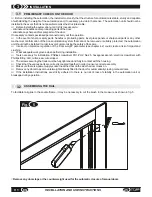
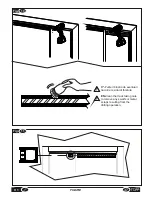
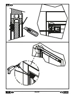
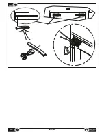
It is possible to adjust the automation's internal sensor detection area by covering the detect window with one ( or more
toghether ) of the covering masks contained in the package
(Fig.24)
.
If the sensor's detection area is too far away from the door, use a label type 'b-c';
If the sensor's detection area is too broad at the sides of the door, use a label type 'd-e-f';
If the detection area is too broad in both directions, use label 'a' or several labels together.
4.5
RESET PROCEDURE
The reset procedure can be used to restore normal door operation following any alarms that caused the system to go into
block mode.
WARNING: During the procedure do not disconnect the power, do not open or close the door manually and do
not touch any of the keys on the electronic board.
WARNING
:
During the initialization and reset procedures all controls (sensors, remote controls, etc.) are
blocked. Therefore, stand clear of the door operating area.
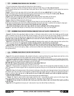
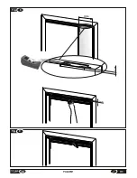
Access the automation unit's electronic circuit board as shown in
fig.20.
-
Figure 22:
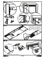
This procedure can be initiated by holding down button S1 for 2 seconds or by pressing reset button 7 on the
remote control. On receiving the command, the door will open very slowly and then close again at the normal set speed.
Once closed the door will go into standby mode, restoring normal operation. The door open time during the reset cycle is
much longer than in a normal cycle.
Default settings provide for very slow opening / closing speed and for automatic reset in the event of lack of
supply voltage. For more details see Section 4.3.
Note: the Pull&go function becomes active once again 5 seconds after the reset procedure is completed.
.
After the reset procedure, close the sliding cover on the board.
4.7
TIMER MODE OPENING AND CLOSING FUNCTION
CAUTION: to use this function it is necessary to have a TS8 remote control, EB1 electric lock and two Hs2
touch controls.
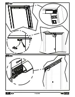
To activate the timer mode function, extract the internal sensor, remove the connector then insert it back into its housing,
while making sure that the flat sensor cables are neatly arranged inside the actuator.
Mount the two HS2 touch controls, one inside and the other outside the room. Lastly, connect the cables of the two touch
controls as follows:
Ÿ
HS2 inside room:
terminal E
in Fig.
22.
Ÿ
HS2 outside room:
terminal D
in
Fig. 22.
Next, shift
dip switches 6
and
7
to
ON
and run a reset procedure as described in
Par 4.5.
After 24 seconds from the end
of the reset, electric lock EB1 will activate to lock the door.
The timer mode function allows for unlocking the door by means of a command
activated through the first button on the TS8 remote control. At this point, the
EB1 electric lock will deactivate and the green light will appear in the HS2 touch
controls. This mode will remain active for 24 seconds before the door locks again.
while the electric lock is deactivated, the door can be opened by touching the
HS2 touch control. Once the door closes, the electric lock will reactivate and
prevent opening of the door from the outside (HS2 with red light). To exit from
inside the door, simply touch the internal HS2 touch control and the door will
open. Once the door closes again, it will return to its initial status with the electric
lock activated.
If the door is unlocked while a person is inside the room, he/she can touch the
HS2 touch control to re-lock the door and subsequently touch the control again
to unlock and open the door. Lastly, if – with the door open – the HS2 touch
Control is kept pressed, the door will remain open and will close once the button
is released.
Moreover, the above function can be enabled or disabled through the Ts8
remote control. To activate and deactivate the «timer mode opening and closing
function», press the fifth function (third button) on the TS8 remote control.
HS2 outside room
HS2 inside room
Содержание V1
Страница 2: ...2 ISTRUZIONI PER L INSTALLAZIONE E L USO IT V1 ...
Страница 35: ...IT 7 FIGURE Fig 6 misura measurement X Fig 7 2cm 35 V1 FIGURE max 250mm A ...
Страница 36: ...Fig 9 Fig 8 250mm 12mm 12mm 36 FIGURE V1 ...
Страница 40: ...10 Fig 20 Fig 19 V1 FIGURE 40 ...
Страница 41: ...Fig 21 41 V1 FIGURE ...
Страница 43: ...Fig 23 TOPP V1 TOPP V1 43 V1 FIGURE ...
Страница 44: ...Fig 24 a b c d e f V1 FIGURE 40 44 ...
Страница 45: ... 45 V1 FIGURE ...
Страница 46: ... V1 FIGURE 40 46 ...
Страница 47: ......

