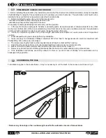
After making this adjustment, connect the actuator to the power supply to perform the initialization procedure.
F
Before performing the initialization procedure, open the door manually by about 10 cm. This is necessary only at the
time of starting the automation.
WARNING: During the procedure do not disconnect the power, do not open or close the door manually and do
not touch any of the keys on the electronic board.
WARNING
:
During the initialization and reset procedures all controls (sensors, remote controls, etc.) are
blocked. Therefore, stand clear of the door operating area.
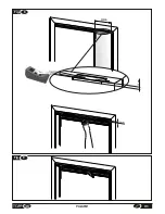
Access the automation unit's electronic circuit board as shown in
fig.20.
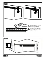
If the cover does not slide easily, remove the actuator from its location and try again
.
-
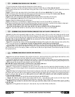
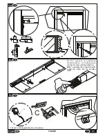
Figure 22
: Press key S1 for about seven seconds. At this point the automation will start the procedure of searching for
the limit switches; wait until it has completed this process. The door performs two opening and closing cycles, after which
the automation is ready to use.
WARNING! The initialisation procedure must be repeated each time the automation unit is given new settings.
After initialization, the "standing by for open command" status is confirmed by LED L2 on with fixed green light.
This status remains unchanged until the door is commanded to open, and returns at the end of the open/close cycle.
If, during the initialization procedure, the door does not reach the limit switches correctly, repeat the procedure,
accompanying the door so that it completes the cycle. This situation could indicate the presence of excessive friction on
the glide of the door, excessive weight of the door or an improper reading of its position by the actuator.
If the door does not move correctly after the second initialisation procedure, check there are no obstacles or impediments,
check the weight of the door and change the settings if required. Repeat the initialisation procedure.
If the problem persists, disconnect the automation unit from the power supply and contact the technical assistance
service.
Note: the Pull&go function becomes active once again 5 seconds after the initialisation procedure is completed.
After the initialization procedure, close the sliding cover on the board.
29
EN
INSTALLATION AND USE INSTRUCTIONS
V1
4.4
INITIALISATION PROCEDURE
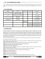
There are 10 dipswitches (microswitches) on the circuit board, accessible by opening the cover on the control board
(Figure 20).
Each dip-switch (Figure 22 reference “C”) can be set in 2 positions, marked ON and OFF.
At the first use, all the dipswitches are set in the OFF position except dips 9-10, which is set to ON.
Hereafter we indicate the functions of each dipswitch.
-DIP-SWITCH No.10:
When set to
ON
, in case of power outage, the reset procedure is performed automatically when
power returns. If set to
OFF
the automation unit awaits a manual reset procedure.
In case of collision:
if set to
OFF
, when an impact occurs the automation unit cuts off the power supply and runs a reset
procedure after 5 seconds; in case the obstacle remains, the door panels remain free until the manual reset procedure
has been performed. If set to
ON
, in the event of collision the door automatically performs a reset; following the fourth
impact, the automation unit cuts off the power supply to the motor for 15 minutes, after which it automatically carries out
the reset procedure.
-DIP-SWITCH No. 9:
If switch to the
ON
position, makes the door close very slowly, regardless of the weight selected on
switch "A".
-DIP-SWITCH No. 8:
: When set to
ON
, causes the door to stop gradually when opening (soft stop). This function was
created for relatively lightweight doors; if the door is moderately or very heavy, the door may not complete the opening
cycle, so it is advisable to set it to the
OFF
position.
-DIP-SWITCH No. 7:
If electric lock EB1 (optional accessory), or another device is fitted, set to
ON
; if no electric lock is
present, set to
OFF
.
-DIP-SWITCHES no. 6-5-4-3-2-1:
These are used to set the door address. In case of a single door, all the dip-switches
must be set to
OFF
.
4.3
PROGRAMMING THE DIP-SWITCH
Содержание V1
Страница 2: ...2 ISTRUZIONI PER L INSTALLAZIONE E L USO IT V1 ...
Страница 35: ...IT 7 FIGURE Fig 6 misura measurement X Fig 7 2cm 35 V1 FIGURE max 250mm A ...
Страница 36: ...Fig 9 Fig 8 250mm 12mm 12mm 36 FIGURE V1 ...
Страница 40: ...10 Fig 20 Fig 19 V1 FIGURE 40 ...
Страница 41: ...Fig 21 41 V1 FIGURE ...
Страница 43: ...Fig 23 TOPP V1 TOPP V1 43 V1 FIGURE ...
Страница 44: ...Fig 24 a b c d e f V1 FIGURE 40 44 ...
Страница 45: ... 45 V1 FIGURE ...
Страница 46: ... V1 FIGURE 40 46 ...
Страница 47: ......


