25
EN
INSTALLATION AND USE INSTRUCTIONS
V1
IT
INSTALLATION
3
3.1
PRELIMINARY CHECKS ON THE DOOR
&
Before installing the automation, the installer must verify that the structure for automation is stable, sturdy and capable
of withstanding the weight of the automation and, if necessary provide in that sense. The automation unit should not be
installed in the event that it is not possible to make the structure stable.
&
Before installing the automation unit, it is first necessary to:
- eliminate all handles and/or protruding parts of the door;
- eliminate any sharp and/or spiky parts of the door;
If necessary contact specialised personnel to carry out the operation.
&
In the event of sharp or spiky parts, handles or protruding parts, inset glass panels or sharpened parts or any other
mechanical conformation of the door-automation system that cannot be removed or suitably protected, the automation
unit should not be installed in order to avoid compromising the safety of the same.
&
Incorrect or imprecise regulation of the “door weight” parameter (see chapter 4.2) could create a risk of impact and
crushing.
&
Wear adequate work gloves when performing installation.
&
Tools necessary for installation: Phillips screwdriver PH1-PH2; No.2,5 hexagonal wrench; electric screwdriver with
Phillips fitting; drill ; cutter; saw; wire stripper.
&
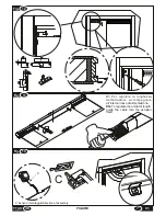
The screws securing the track must be fully tightened and fully in contact with the housing.
&
Check that the various parts are correctly coupled together in order to ensure correct assembly.
&
Make sure there is a power supply socket near the door on the side the door closes on.
&
Remove any door stops or counterweights already fitted to the door for automatically closing manual doors.
&
If the installation instructions are strictly adhered to there is no risk of loss of stability in the automation unit or
breakage during operation.
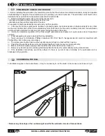
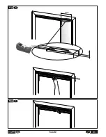
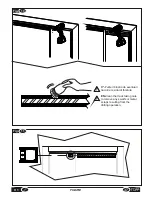
To facilitate rail glide in the counterframe, it may be necessary to cut the brush in the measure as shown in fig. 5.
3.2
ASSEMBLING THE RAIL
F
Remove any doorstops or the counterweight used for the automatic closure of manual doors
Fig.
5
60
Содержание V1
Страница 2: ...2 ISTRUZIONI PER L INSTALLAZIONE E L USO IT V1 ...
Страница 35: ...IT 7 FIGURE Fig 6 misura measurement X Fig 7 2cm 35 V1 FIGURE max 250mm A ...
Страница 36: ...Fig 9 Fig 8 250mm 12mm 12mm 36 FIGURE V1 ...
Страница 40: ...10 Fig 20 Fig 19 V1 FIGURE 40 ...
Страница 41: ...Fig 21 41 V1 FIGURE ...
Страница 43: ...Fig 23 TOPP V1 TOPP V1 43 V1 FIGURE ...
Страница 44: ...Fig 24 a b c d e f V1 FIGURE 40 44 ...
Страница 45: ... 45 V1 FIGURE ...
Страница 46: ... V1 FIGURE 40 46 ...
Страница 47: ......

