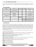
The table below indicates the approximate specific weights of the main materials used for the construction of doors, for
calculation of the volume and weight of the door. Topp has no liability as regards the calculation of wing weight and the
material of which it is made.
SPECIFIC WEIGHT (Ps)
MATERIALS
2600 g/m³
GLASS
300 kg/m³
600 kg/m³
800 kg/m³
LIGHT HOLLOW-CORE PANELS
HEAVY HOLLOW-CORE PANELS
SOLID WOOD
Where:
V
= volume of the wing expressed in cubic millimeters
L=
width of the wing in meters
H=
height of the wing in meters
S=
thickness of the wing in meters
Where
:
P=
weight of the wing expressed in Kg
V=
volume of the wing expressed in cubic millimeters as calculated above
Ps=
specific weight of the material of which the wing is made, expressed in kg./cu.mm.
V
=
L
x
H
x
S
P
=
V
x
Ps
The volume of the wing is given by the following formula
The weight of the wing is given by the following formula
28
INSTALLATION AND USE INSTRUCTIONS
EN
V1
“ultraslow” function
door off, motor disabled
The door open time can also be regulated by adjusting the trimmer
“B”(figure 22)
, accessing the electronic circuit board
in the automation unit (fig.20). The door open time can be regulated between a minimum of 2 seconds and a maximum of
60.
4.2
PROCEDURE FOR ADJUSTMENT OF THE WEIGHT AND OPENING TIME
Before activating the automation unit, the opening and closing speed must be regulated to match the door
weight by accessing the electronic circuit board in the automation unit (see fig.20).
The table below indicates the position of trimmer
“A” (Figure 22)
in relation to the wing weight. The switch is turned to “A”
in the factory. This condition can be considered safe for all types of disappearing doors weighing less than 50 kg.
Adjustment of the switch should be made only if the weight of the door to be driven is certain.
Improper setting can cause malfunction of the automation as well as hazardous behavior of the door.
POSIZIONE
PESO ANTA
Position 1
Position 2
Position 3
Position 4
Position 5
Position 6
Position 7
Position 8
Position 9
Position A
Position 0
da 15 kg
a 18 kg
Position E
Position F
da 18 kg
a 21 kg
da 21 kg
a 24 kg
da 24 kg
a 27 kg
da 27 kg
a 30 kg
da 30 kg
a 33 kg
da 33 kg
a 36 kg
da 36 kg
a 39 kg
da 39 kg
a 42 kg
da 42 kg
a 45 kg
da 45 kg
a 50 kg
Position B
da 50 kg
a 55 kg
Position C
da 55 kg
a 60 kg
Position D
da 65 kg
a 70 kg
Содержание V1
Страница 2: ...2 ISTRUZIONI PER L INSTALLAZIONE E L USO IT V1 ...
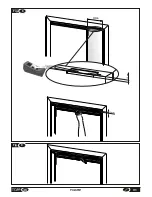
Страница 35: ...IT 7 FIGURE Fig 6 misura measurement X Fig 7 2cm 35 V1 FIGURE max 250mm A ...
Страница 36: ...Fig 9 Fig 8 250mm 12mm 12mm 36 FIGURE V1 ...
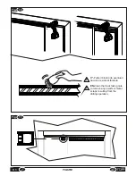
Страница 40: ...10 Fig 20 Fig 19 V1 FIGURE 40 ...
Страница 41: ...Fig 21 41 V1 FIGURE ...
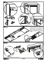
Страница 43: ...Fig 23 TOPP V1 TOPP V1 43 V1 FIGURE ...
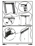
Страница 44: ...Fig 24 a b c d e f V1 FIGURE 40 44 ...
Страница 45: ... 45 V1 FIGURE ...
Страница 46: ... V1 FIGURE 40 46 ...
Страница 47: ......


