26
INSTALLATION AND USE INSTRUCTIONS
EN
V1
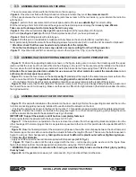
3.5
ASSEMBLING THE ACTUATOR ON THE WING
-
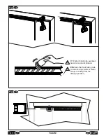
Figure 15
: Proceed with installation of the actuator on the door, inserting it first on the supporting bracket and then on the
rail rotor connecting guide previously installed.Proceed to install the actuator on the door.
F
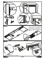
Position the actuator as shown in the figure 15 at number 1. This position is approximate and will need later adjustment.
-
Figure 16
: Position the actuator on the side of the plug (see figure 16) on the connection guide, gently sliding the same
until the actuator interlocks with the dedicated housing on the track.
IMPORTANT: Support the actuator until it has been completely fastened.
Permanently fasten the actuator with the four screws AF TC 3x16.
-
Figure 17
: If the actuator is not parallel to the door,remove the actuator from the supporting bracket and place it on the
other housings of the lateral plug so that it is as parallel as possible to the door. At this point fasten the special M4 x20 Tsh
Ph screw.
-
Figure 18
: Make the final adjustment of the actuator length,leave a few millimeters of space between the door frame and
the lateral cap on the rotor side so as to allow the actuator to follow the length of the rail. Than secure the bolts loosened in
figure 13 using a 2.5mm hexagonal key
taking extra care not to deform the plastic outer surface (tightening torque -
1.7Nm). See fig.18 detail A.
F
Apply over the screws the two red labels supplied with the package
(ref.12 fig. 2).
F
-
Figure 19
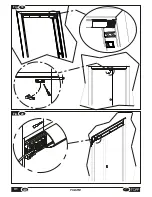
: Open the door until the rail is aligned with the rotor – rail connecting guide as shown in the figure. Now
fasten the safety stop from the side opposite the automation, using two TSP 2.5x20 screws.
F
WARNING: Only activate the actuator after having secured the safety blocks and tested their grip by pulling
them by hand.
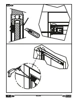
- Figure 23:
Cut the gaskets to measure (ref.: component 5, Fig. 2) and insert them into the slots
.
-
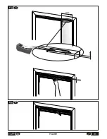
Figure 12
:Position the supporting bracket as shown in the figure, taking care to ensure that it rests against the upper
jamb and that the inner lip of the bracket fits into the stripping on the jamb. The bracket should be installed on the side of
the door where the rail has already been installed. Fasten the bracket to the frame using three TSP2.5x20 screws .
Attention: the screws provided are suitable for use on wood, for other materials contact the manufacturer or an
authorised technical assistance centre.
-
Figure 13
: Loosen the four screws on the back
(see fig.13 )
and adjust the length to the same measurement as that of the
door, minus about 20 mm.
To regulate the actuator length, guide the cable into the actuatori itself.
F
Do not fasten the screws at this point as adjustments will be necessary later along the length of the actuator.
-
Figure 14
: Make sure that the flat cables for the sensor (component 4 fig. 2) are arranged tidily inside the actuator and
then insert the sensor into its housing. Make sure the sensor is fitted in the right direction (the detection window should be
facing downwards).
3.4
ASSEMBLING THE SUPPORTING BRACKET AND ACTUATOR PREPARATION
3.3
ASSEMBLING THE RAIL ON THE WING
F
The same procedure is followed for both directions of door opening.
-Figure 6
: Close the door flush with the jamb and mark the point where they meet.
See measurement X.
F
If the space between the door and the base of the jamb leaves room to fit the rail inside it, you can fasten the rail in line
with the door.
-Figure 7
: perform the measurement of the transit space and cut the rail,
see detail A fig.7
to correct cutting.
Drill the rail using a 3mm bit: drill 4 holes at the edges and the remaining ones all along the rail
every max. 250mm.
Take care not to damage, twist or misshape the rail in any way.
-Figure 8:
Place the rail templates
(fig. 2 part 7)
against the jamb at the top and tape it to the jamb.
Set the rail
(see figure 2 part 2)
at the top of the templates beside the X you have just marked.
-Figure 9
: Mark the drilling points with a felt-tip pen .
-
Figure 10
: At this point, it is advisable to make preliminary holes on the door to facilitate screw fastening .
Next, permanently fasten the rail with the self tapping screws for aluminum 2,9x13 or with the 3x16 screws for chipboard.
F
Attention: check that the screw heads do not protrude from the rail profile.
F
Clean the track taking care to remove any swards or scraps resulting from the drilling operation
-Figure 11
: Open the door and fit the connecting runner in the rail (part no. 3, fig. 2), so that it glides.
Содержание V1
Страница 2: ...2 ISTRUZIONI PER L INSTALLAZIONE E L USO IT V1 ...
Страница 35: ...IT 7 FIGURE Fig 6 misura measurement X Fig 7 2cm 35 V1 FIGURE max 250mm A ...
Страница 36: ...Fig 9 Fig 8 250mm 12mm 12mm 36 FIGURE V1 ...
Страница 40: ...10 Fig 20 Fig 19 V1 FIGURE 40 ...
Страница 41: ...Fig 21 41 V1 FIGURE ...
Страница 43: ...Fig 23 TOPP V1 TOPP V1 43 V1 FIGURE ...
Страница 44: ...Fig 24 a b c d e f V1 FIGURE 40 44 ...
Страница 45: ... 45 V1 FIGURE ...
Страница 46: ... V1 FIGURE 40 46 ...
Страница 47: ......

