4.6
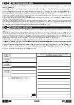
LIST OF MESSAGES AND ALARMS
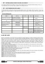
STATUS MESSAGES
LED L1
LED L2
MESSAGES
ALTERNATING RED /GREEN
ALARM
GREEN LIGHT ON CONSTANT
RED LIGHT ON CONSTANT
CONSTANT FLASHING
GREEN LIGHT
OFF
DOOR WAITING
PAUSE FOR REMOTE
LEARNING
DOOR LOCKED
BY REMOTE CONTROL
1 BLINK PLUS X BLINKS
IN RELATION TO ALARM NO.
LED L3
LED L4
GREEN LIGHT
ON CONSTANT
24 V POWER ON
SLOW YELLOW
FLASHING LIGHT
DOOR STOPPED AND NO
MODBUS COMMUNICATION
RAPID YELLOW
FLASHING LIGHT
MODBUS COMMUNICATION
OR GUIDED READING
4.5
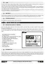
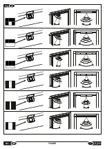
INTERNAL SENSOR DETECTION AREA ADJUSTMENT
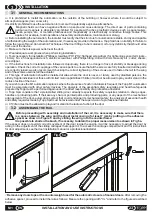
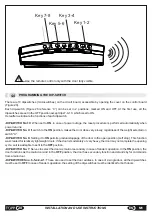
It is possible to adjust the automation's internal sensor detection area by covering the detect window with one ( or
more toghether ) of the covering masks contained in the package (Fig.27 ).
GREEN LIGHT
ON CONSTANT
GREEN LIGHT
ON CONSTANT
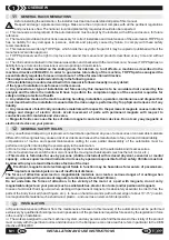
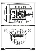
The M1 automation continuously verifies its operating status and can communicate, with the two leds L1 and L2, any
malfunctions or particular states. The table below lists the possible messages. Refer to Figure 26 for the position of the
leds.
29
EN
INSTALLATION AND USE INSTRUCTIONS
M1
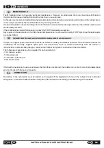
If there is a malfunction on the system that could make the machine dangerous or hinder its operation, the M1 actuator
stops movement of the door and led L1 will signal the alarm by blinking alternately red/green. To identify the cause of the
stoppage, just count the number of consecutive red blinks of the other led, L2. The message is repeated cyclically and
therefore there will be a sequence of blinks, a pause in which the led is off and a new sequence of blinks. There may be
more than one alarm at the same time. In this case the messages will appear consecutively, one after the other. For
example, in case of alarms 1 and 4, the sequence of blinks will be: one blink, pause, four blinks, pause, one blink, pause,
for blinks, pause, one blink,…
To restore operation of the door just perform the “reset” procedure by pressing S1 or the reset key on the remote control.
The following is the list of alarm messages:
-
Alarm 1
: Generic alarm condition of machine, any malfunction causes the initial blink, which will be followed by a fixed
number of blinks indicating the type of alarm.
-
Alarm 3
: Excessive speed of door opening and closure causing unsafe condition.
-
Alarm 4
: Maximum number of collisions reached in closure.
-
Alarm 5
: Internal board of CPU overheated.
-
Alarm 6
: At the end of the initialization procedure, the measurement reading of the door is outside of the machine
parameters (between 700 and 1,000mm).
-
Alarm 7
: time out for measurement – the door measurement cycle did not end in the time foreseen.
-
Alarm 8
: time out for setting – the initialization cycle did not end in the time foreseen.
-
Alarm 9
: Time out on door reset cycle.
-
Alarm 10
: Time out on door opening cycle.
-
Alarm 11
: Time out on door closing cycle.
-
Alarm 12
: Time out on door reversal cycle.
ALARM MESSAGES
Содержание M1
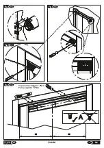
Страница 2: ...2 ISTRUZIONI PER L INSTALLAZIONE E L USO IT M1 ...
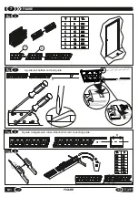
Страница 34: ... 34 FIGURE M1 Fig 11 5 0 Fig 10 ...
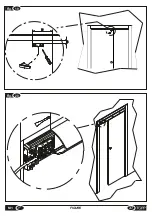
Страница 36: ...Fig 15 Fig 17 1 2 34 5 Fig 16 Fig 18 36 FIGURE M1 Coppia di serraggio 1 7Nm Force equal to 1 7Nm A ...
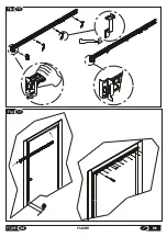
Страница 37: ...Fig 19 75 10 Fig 20 37 M1 FIGURE ...
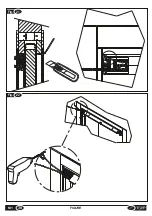
Страница 38: ... M1 FIGURE 38 Fig 21 Fig 22 ...
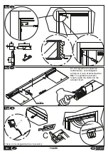
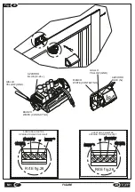
Страница 40: ... M1 FIGURE 40 Fig 70mm 24 Fig 25 TOPP M1 TOPP M1 ...
Страница 42: ... M1 FIGURE 42 Fig 27 ...

