24
INSTALLATION AND USE INSTRUCTIONS
EN
M1
3.5
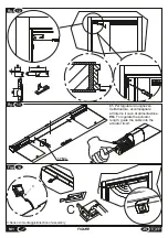
ASSEMBLING THE ACTUATOR ON THE WING
-
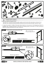
Figure 15
: Proceed with installation of the actuator on the door, inserting it first on the supporting bracket and then on the
rail rotor connecting guide previously installed.Proceed to install the actuator on the door. Magnetic force will attract the
rotor toward the rail holding the actuator in place.
Position the actuator as shown in the figure at number 1. This position is approximate and will need later adjustment.
-
Figure 16
: Fasten the rotor to the connecting guide using the four 2.9x16 screws, making sure they are correctly fitted.
-
Figure 17
: If the actuator is not parallel to the door,remove the actuator from the supporting bracket and place it on the
other housings of the lateral plug so that it is as parallel as possible to the door. At this point fasten the special M4x20
screw.
-
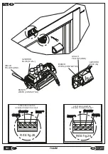
Figure 18
: Make the final adjustment of the actuator length,leave a few millimeters of space between the door frame and
the lateral cap on the rotor side so as to allow the actuator to follow the length of the rail. Then fasten the loose screws in
figure 13, fixing with a No.2.5 hexagonal wrench
with force equal to 1.7Nm.
Be careful not to deform the outer surface of plastic. See fig.18 detail A
. Apply over the screws the two red labels
supplied with the package (ref.15 fig. 2).Cut the gaskets to measure (ref.5 fig.2) and insert them into the slots (Fig. 25).
-
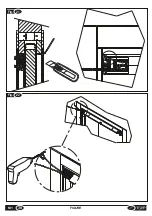
Figure 19
: On the side opposite the automation, fasten the safety stop in the positions shown in the figure, using the
2.5x20 screws .
IMPORTANT: Start the actuator only after fastening the safety stop and testing its tightness.
The same procedure is followed for both directions of door opening.
-
Figure 12
:Position the supporting bracket as shown in the figure, taking care to ensure that it rests against the upper
jamb and that the inner lip of the bracket fits into the stripping on the jamb. The bracket should be installed on the side of
the door where the rail has already been installed. Fasten the bracket to the frame using two 2.5x20 screws.
-
Figure 13
: Before installing the actuator on the door, loosen the four screws on the back (see fig.13 ) and adjust the
length to the same measurement as that of the door, minus about 20 mm.
To regulate the actuator length, guide the
cable into the actuator itself
Do not fasten the screws at this point as adjustments will be necessary later along the length of the actuator.
-
Figure 14
: Make sure the flat cables are arranged in an orderly manner inside the actuator, then fasten the sensor, with
attention to the direction of assembly (the inspection window should be positioned facing downward) .
3.4
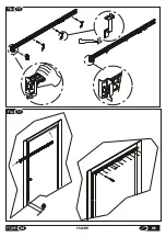
ASSEMBLING THE SUPPORTING BRACKET AND ACTUATOR PREPARATION
To install the rail assembled previously, proceed as follows:
-
Figure 10
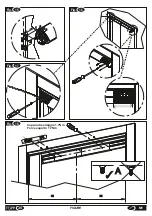
: Apply the installation templates of the rail as shown in the figure, fitting them in the housing of the track guides
on the rail and taking care to apply the appropriate one at the head.The head template has been designed for a depth of
the jamb <= 10mm. For deeper measurements do not use the template, but regulate the position of the rail so that it does
not interfere with door closure.
-
Figure 11
: Open the door by about 50 mm and insert the rail in the space between the wing and the sheet metal case;
position the installation templates so that they abut the upright at the top and on the edge of the door, ascertain that the rail
is parallel with this latter and fasten it using the 12 TSP screws for chipboard measuring 2.5x20 or aluminum 2.5x16,
distributing them along the entire length of the rail. Make sure the rail is securely fastened, then remove the
templates.Under particular conditions, when it is difficult to install the rail, it is advisable to drill the holes in advance to
facilitate fastening the screws. We recommend using a 1.5 mm bit.
3.6
ASSEMBLING AND CONNECTING THE MICROWAVE OR INFRARED SENSOR (optional)
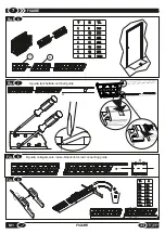
3.3
ASSEMBLING THE RAIL ON THE WING
Figure 6:
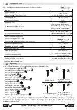
Join the parts of the rail, selecting the number of parts to assemble in the basis of the table shown.For
intermediate measurements, select a number of elements in excess.
Figure 7:
On the two end sections of the rail (top and bottom) insert the two track profiles flush with the end of the head
section.
Important note: the guides shall be fitted with the notch on the side of the head component.
It is important that the notched guide is positioned, after installing the rail on the wing, on the lower section if the door
opens toward the right and on the upper section if the opening is on the left (as seen from the front of the
automation).See Par.2.5 Fig.3,4.
Then turn the track and bend, using a screwdriver, the two head wings up to close them perfectly on the component.
Figura 8
: On the two guides, fit the rotor-rail connecting guide necessary for fastening the automation to the rail (see
component 3 in fig. 2);
Figura 9
: Cut the two rail tracks to size with the saw provided
.
To install the microwave or infrared sensor on the side opposite the automation, proceed as follows:
-
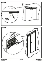
Figure 20
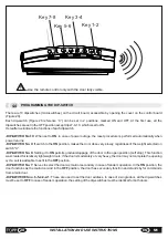
: Move the extruded cover as shown in the figure so as to expose the electronic board on the inside.
If the cover does not slide easily, remove the actuator from its location and try again.
-
Figure 21:
Insert the sensor wire in the upper space between the lateral cap for fastening to the bracket and the upper
jamb of the door. Push the wire into the gap usually found above the door jamb, as described in Figure 21, and bring it out
on the opposite side with enough length to reach the sensor position. Make sure the thickness of the wire does not
interfere with correct closure of the door. If necessary, create additional space for the wire to pass by remove the upper
part of the door stripping with the cutter. Make sure the wire does not move out of place by using adequate fasteners (such
as duct tape or special clips for round wire). Connect the end of the wire to terminal E as shown in Figure 26 following the
instructions in Figure 23.
If a TOPP IS4 infrared sensor is installed, the blue wire should be fastened to terminal 5V.
Содержание M1
Страница 2: ...2 ISTRUZIONI PER L INSTALLAZIONE E L USO IT M1 ...
Страница 34: ... 34 FIGURE M1 Fig 11 5 0 Fig 10 ...
Страница 36: ...Fig 15 Fig 17 1 2 34 5 Fig 16 Fig 18 36 FIGURE M1 Coppia di serraggio 1 7Nm Force equal to 1 7Nm A ...
Страница 37: ...Fig 19 75 10 Fig 20 37 M1 FIGURE ...
Страница 38: ... M1 FIGURE 38 Fig 21 Fig 22 ...
Страница 40: ... M1 FIGURE 40 Fig 70mm 24 Fig 25 TOPP M1 TOPP M1 ...
Страница 42: ... M1 FIGURE 42 Fig 27 ...

