


3.7
RESIDUAL HAZARDS
The analysis of essential safety requisites for safeguarding health, performed by TOPP SpA on the basis of Machine
Directive 2006/42/CE, refers to a “typical” installation site and user adequate for the type of machine that will be produced.
It is therefore necessary to indicate some residual hazards that are not protected:
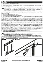
1) Risk connected with the solidity, state of wear and quality of installation of the door to be motorized.
2) Risk connected to loss of stability due to improper fastenings due to negligence on the part of the installer of the
automation.
3) Risk due to possible sharp or pointed edges already existing at the site to be motorized and not adequately protected by
the installer of the automation.
4) Risk of catching, hooking and cutting due to the presence of handles, glass inserts, protruding or sharp parts existing at
the site to be motorized and not adequately protected by the installer of the automation.
5) Risk of impact and crushing if the installer of the automation does not scrupulously perform adjustment of the “door
weight”.
6) Risk of impact and crushing if the automation is installed in rooms where the door is subject to frequent use by the
elderly, children, disabled or, in any case, fragile individuals, without taking adequate safety precautions.
Any procedure or type of installation not foreseen or not mentioned by this manual is to be considered not
covered by this analysis of essential safety requsites for the protection of health and safety carried out by TOPP
SpA and therefore the installer will have to perform the complete analysis again under his responsibility.
IT
USE AND OPERATION
4
4.1
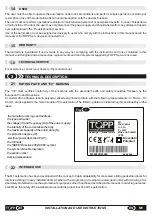
TECHNICAL DESCRIPTION
The automation is a magnetic type with no clutch or brakes, so as to prevent possible blockages of a continuous character
due to damage or breakage of the structure.
The power supply is 230V~ 50 Hz.
The glide rail for the automation consists of permanent magnets.
The electronic command and control board is a microprocessor type with keys along the edge for adjustment of such
parameters as speed of opening and closing, slowing space, low approach speed, automatic return to the closed position,
timing and mode of operation.
The automation is equipped with various functions, such as:
-Pull & go, which permits automatic movement of the door if pushed or pulled slightly;
- ultraslow nighttime function (can be selected with the remote control), which reduces the noise;
- the possibility of connection of two-wing doors using the communication protocol;
- the possibility of connection to the domotic network via Bus (up to 63 actuators usable in a single network);
- the possibility of updating the software through the serial input on the programming board.
In case of power outage, there is an automatic door reset function.
The M1 automation has been designed so that the door, under good conditions, can be moved with a strength of not more
than 220 N, to prevent the risk of trapping.
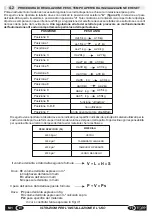
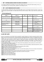
4.2
PROCEDURE FOR ADJUSTMENT OF THE WEIGHT, OPENING TIME, INITIALIZATION AND RESET
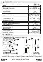
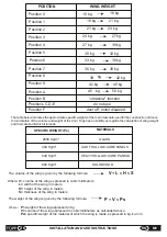
Before enabling the automation it is necessary to regulate the opening and closing speed in relation to the door weight.
The table below indicates the position of trimmer
“A” (Figure 26)
in relation to the wing weight.The switch is turned to “A”
in the factory. This condition can be considered safe for all types of disappearing doors weighing less than 50 kg.
Adjustment of the switch should be made only if the weight of the door to be driven is certain.
Improper setting can cause
malfunction of the automation as well as hazardous behavior of the door.
25
EN
INSTALLATION AND USE INSTRUCTIONS
M1
-
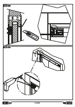
Figure 22
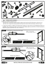
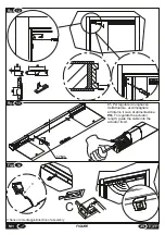
: As an alterative to passage of the wire as described in Figure 21, drill the wall with a suitable drill, taking care
not to let dust or scraps fall on the rail or actuator, with an 5mm bit and connect one end of the sensor wire to connector E in
Fig. 26, following the instructions in Fig. 23.
If a TOPP IS4 infrared sensor is installed, the blue wire should be
fastened to terminal 5V.
Insert the sensor wire in the opening just drilled so that it protrudes by at least 70 cm from the
other side.
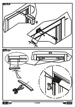
-
Figure 24
: At this point drill suitable holes at the midline of the door and insert the two 4x20 bolts for light fastenings
(supplied). Run the sensor wire above the door frame and thread it through the hole in the fastening base of the sensor so
that it protrudes by at least 70 mm (see figure). Secure the fastening base with two AF TSP d3x25 screws.
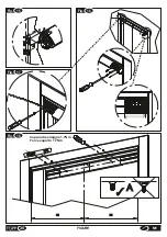
-
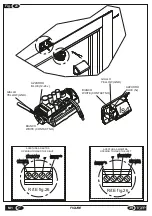
Figure 25
: Connect on the other end of the wire to the connector on the electronic board of the sensor, paying attention to
the positioning of the wires . Apply the assembled electronic board and sensor on the fastening base, then fasten the front
cover. Apply the wire clamp cover (component 12 fig.2 ) on the magnetic motor , taking care not to let the wires overlap one
another.
Содержание M1
Страница 2: ...2 ISTRUZIONI PER L INSTALLAZIONE E L USO IT M1 ...
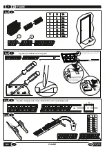
Страница 34: ... 34 FIGURE M1 Fig 11 5 0 Fig 10 ...
Страница 36: ...Fig 15 Fig 17 1 2 34 5 Fig 16 Fig 18 36 FIGURE M1 Coppia di serraggio 1 7Nm Force equal to 1 7Nm A ...
Страница 37: ...Fig 19 75 10 Fig 20 37 M1 FIGURE ...
Страница 38: ... M1 FIGURE 38 Fig 21 Fig 22 ...
Страница 40: ... M1 FIGURE 40 Fig 70mm 24 Fig 25 TOPP M1 TOPP M1 ...
Страница 42: ... M1 FIGURE 42 Fig 27 ...


