


Chapter 2 Wiring
2.1 Wiring specification
Wire diameter: R, S, T, PE, U, V, W terminal wire diameter ≥ 1.5mm
2
(AWG14-16), r, t
terminal wire diameter ≥
0.75mm
2
(AWG18)
。
The terminals are pre-insulated cold-pressed terminals and must be firmly connected.
It is recommended to use a three-phase isolation transformer for power supply
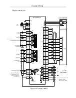
2.2 Wiring method
For the input/output signal line and the encoder signal line, use the recommended cable or
similar shielded cable. The wiring length is: Input/output signal line is 3m or less, and
encoder signal line is 20m or less.When wiring, connect at the shortest distance. The
shorter the better, the main circuit wiring and signal line should be separated.
The grounding wire should be thick and made a little grounded. The grounding terminal of the
servo motor and the grounding terminal of the servo driver pe
Be sure to connect.
To prevent malfunction caused by interference, it is recommended to install a noise filter and
note that:
1) The noise filter, servo driver and host controller are installed as close as possible.
2) Surge suppressors must be installed in coils such as relays, electromagnetic contactors, and
brakes.
3) Do not pass the main circuit and signal lines through the same pipe and do not tie them
together.
When using strong interference sources nearby (such as electric welders, electric spark
machines, etc.), using an isolation transformer on the input power supply can prevent
malfunctions caused by interference.
Install a non-fuse type circuit breaker (nfb) to cut off the external power supply when the drive
fails.
Connect the cable shield correctly.
2.3 Precautions
The terminals of the drivers u, v, and w must be in one-to-one correspondence with the
motor terminals u, v, and w. Note that the motor cannot be reversed by changing the
three-phase terminals, which is completely different from the asynchronous motor.
Since the servo motor flows through the high-frequency switching current, the leakage
current is relatively large, and the motor ground terminal must be connected to the servo
driver ground terminal pe and grounded well.
Содержание SD300
Страница 87: ......
Страница 89: ...Chapter 7 Running 7 9 2 Operation l Set the parameter values ...


