background image

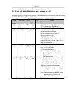
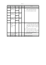
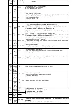
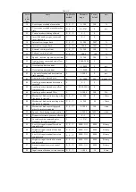
Termi

nal

numbe

r

Signal

name

mark the

way

CN1-

11

Comma

nd

pulse

prohi

bition

INH

P

Position command pulse inhibit input terminal

Inh:on command pulse input is forbidden

Inh:off command pulse input is valid

Speed

selection

2

SC2

S

Speed

​​

selection 2 input terminal

In speed control mode, the combination of sc1 and sc2 is used to select different internal speeds.

Sc1:off,sc2:off internal speed 1 sc1:on, sc2:off internal speed 2

Sc1:off,sc2:on internal speed 3

Sc1:on,sc2:on internal speed 4

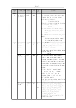
CN1-

12

Ccw

torque

limit

FIL

P,S

Ccw (counterclockwise) torque limit input terminal

FIL: ON Counterclockwise torque limit is within the range of parameter No.36

FIL:OFF Counterclockwise torque limit is not limited by parameter No.36

Note: ccw torque is subject to parameters regardless of whether fil is valid or invalid.

No.34 Limit, in general, parameter No.34> Parameter No.36

CN1-

13

Cw

torque

limit

RIL

P,S

CW (clockwise) torque limit input terminal RIL: ON Clockwise torque limit within parameter

No.37

RIL:OFF Clockwise torque limit is not limited by parameter No.37

Note: cw torque is also affected by parameters, regardless of whether ril is valid or invalid.

No.35 Limit, in general, parameter No35> Parameter No.37

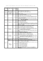
CN1-1 Servo

ready

output

SRDY P,S

Servo ready output terminal srdy:on Control power and main power are normal, AC servo drive

unit has no alarm, servo is ready to output on.

Srdy:off The main power supply is not connected or the AC servo drive unit has an alarm, and

the servo is ready to output off.

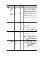
CN1-

15

Servo

alarm

output

ALM

P,S

Servo alarm output terminal

Alm:on The servo unit has no alarm and the servo alarm output is on.

Alm:off servo unit has alarm, servo alarm output is off

CN1-

14

Position

ing

compl

etion

output

COIN

P

Positioning completed output terminal

Coin:on When the position deviation counter value is within the set positioning range, the

positioning completion output is on.

Speed

arriva

l

output

SCMP

S

The speed reaches the output terminal scmp:on When the speed reaches or exceeds the set

speed, the speed reaches the output on.

CN1-3

CN1-4

CN1-

16

CN1-

17

Commo

n end of

the

output

terminal

DG

Ground terminal of control signal output terminal (except cz)

CN1-2 Encoder

z

Phase

output

CZ

P,S

Encoder z phase output terminal

Photoelectric encoder z-phase pulse output of servo motor

Cz:on z phase signal appears

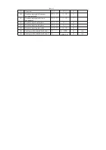
CN1-5

Encoder

z

Commo

n end

of

phase

output

CZC

O

M

P,S Common end of the encoder z-phase output terminal

CN1-

18

Comman

d pulse

Plus lose

Enter

PULS

+

P

External command pulse input terminal

Note: Pulse input mode is set by parameter 04

Command pulse + symbol mode;

Ccw/cw instruction pulse mode;

CN1-6

PULS-

CN1-

19

Comman

d pulse

Sign

input

SIGN+

P

CN1-7

SIGN-

CN1-

24

Brake

negat

ive

level

BZ-

P,S

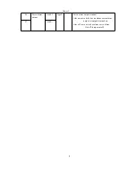
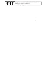
This port can be used to control the brake when the motor has a mechanical brake (power
loss retainer)

Bz on: the brake is energized, the brake is invalid, and the motor can run;

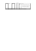
Function 

Содержание SD300

Страница 1: ...Instructional Manual For SD300 TOPCNC Workshop Automation Technology Co Ltd topcncworkshop outlook com whatsapp 8613811674107 ...

Страница 2: ... may result in electric shock or fire It is forbidden to use the product in places with direct sunlight dust salt and metal powder It is forbidden to use the product in places where water oil and drugs Ground the grounding terminal reliably Poor grounding may result in electric shock or fire Do not connect the 220v drive power supply to the 380v power supply Otherwise it may cause equipment damage...

Страница 3: ...ating inside the drive When the motor is running it is forbidden to touch any rotating parts otherwise it will cause casualties Do not touch the driver and motor while the device is running otherwise it may cause electric shock or burns Do not touch the inside of the drive and its motor as this may result in electric shock Do not remove the drive panel when the power is turned on otherwise it may ...

Страница 4: ...conditions in the control cabinet the temperature around the servo drive will continue to rise so considering the cooling of the drive and the configuration inside the control cabinet the long term safe working temperature is below 40 c There is a heating device near the servo drive Servo drives operating at high temperatures can significantly shorten their life and cause malfunctions Therefore th...

Страница 5: ...o drive Installation interval Please refer to Figure 1 1 for the installation distance between the servo drives and other devices Note that the minimum size is indicated on the drawing In order to ensure the performance and life of the drive please leave as much installation interval as possible Heat dissipation The servo drive adopts the natural cooling method and a cooling fan must be installed ...

Страница 6: ...et place the cable outlet below Vertical installation If the motor shaft is mounted upwards and the gear unit is attached care must be taken to prevent oil in the gear unit from penetrating into the motor through the motor shaft The amount of protrusion of the motor shaft needs to be sufficient If the amount of protrusion is insufficient it will easily cause vibration when the motor moves When ins...

Страница 7: ... filter and note that 1 The noise filter servo driver and host controller are installed as close as possible 2 Surge suppressors must be installed in coils such as relays electromagnetic contactors and brakes 3 Do not pass the main circuit and signal lines through the same pipe and do not tie them together When using strong interference sources nearby such as electric welders electric spark machin...

Страница 8: ...ned off there is still a high voltage in the internal circuit After the power is turned off wait at least 5 minutes before touching the drive and motor After turning on the power the operator should keep a certain distance from the drive and motor If it is not used for a long time please cut off the power ...

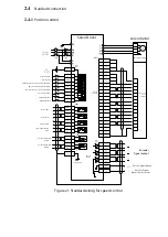
Страница 9: ... selection 1 zero speed clamp Speed selection 2 CCW torque limit CW torque limit Servo ready Servo alarm Speed arrival Mechanical brake freed Position command Position command receiver Motor 4 pin plug Photoelectric encoder 15 pin plug Encoder Signal output Encoder Signal Ground Encoder Z signal Open collector output Case ground Driver 2 4 2 4 1 Standard connection Position control ...

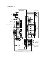
Страница 10: ...G CN1 CN1 CN1 2 3 4 1 3 4 7 5 8 6 9 10 13 11 14 12 15 1 2 AS 19 AS 20 10K AGND 23 FG 36 Z GND M Servo enable Alarm clear CCW counterclockwise drive prohibition CW clockwise drive prohibition Speed selection 1 zero speed clamp Speed selection 2 CCW torque limit CW torque limit Servo ready Servo alarm Speed arrival Mechanical brake freed Speed Control 2 4 2 Figure 2 2 Standard wiring for speed contr...

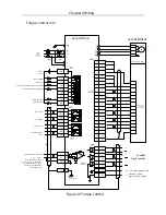
Страница 11: ...ady Servo alarm Speed arrival Mechanical brake freed Note When the software version uses V2 Oi1 the torque analog command is entered into the port 21 22 and the input port is 19 20 Torque simulation command receiver 26LS31 Encoder Signal output Encoder Signal Ground Encoder Z signal Open collector output Case ground Driver Motor 4 pin plug Photoelectric encoder 15 pin plug Figure 2 3 Torque Contro...

Страница 12: ...220v Main circuit power input terminal AC220V 50Hz Note Do not connect to the motor output terminals u v w 3 S 4 T 5 U Servo motor power output Output to the servo motor power supply It must be connected to the motor u v w terminals one to one 6 V 7 W 8 PE Ground Ground terminal connected to the outer casing of the motor 9 r Control power input Single phase ac220v Control loop power input terminal...

Страница 13: ...te Note 1 The motor must be stationary before it is hit from son off to son on Note 2 Wait at least 50ms after hitting SON ON Enter the command again 11 Alarm clear ALRS Type1 Alarm clear input terminal Alrs on Clear system alarm alrs off keep system alarm Note For alarms with a fault code greater than 8 this method cannot be used to clear the alarm Then power up again 12 Ccw driver is forbidden F...

Страница 14: ...ion counter clears the input terminal Cle on position deviation counter during position control Cleared Speed selection 1 SC1 Type1 S In the speed control mode parameter pa4 1 when the internal speed is selected parameter pa 22 0 the speed selects 1 input terminal In the speed control mode the combination of sc1 and sc2 is used to select different internal speeds Sc1 off sc2 off internal speed 1 s...

Страница 15: ...pe1 Ccw counterclockwise torque limit input terminal Fil on ccw torque limit is within the range of parameter pa36 Fil off ccw Torque limit is not limited by parameter pa36 Note Whether fil is valid or invalid ccw torque Also limited by parameter pa34 general parameters Pa34 Parameter pa36 17 Cw torque limit RIL Type1 Cw clockwise torque limit input terminal Ril on cw torque limit in parameter pa3...

Страница 16: ...Interface 26 Servo alarm output ALM Type2 Servo alarm output terminal Alm on servo drive has no alarm servo alarm output is output is turned on Alm off servo drive has alarm servo alarm Out off output cutoff 27 ALM ...

Страница 17: ...he motor has a mechanical brake power loss retainer Brk on the brake is energized the brake is invalid and the motor can run Brk off The brake is cut off the brake is effective the motor is locked and cannot be operated Note The brk function is controlled internally by the drive 31 BRK 32 Command pulse Plus input PULS Type3 P External command pulse input terminal Note The pulse input mode is set b...

Страница 18: ...terface input range 10V 10V Note When the software version uses v2 0 or above the torque analog command input port 21 22 is changed to the input port 19 20 22 AT 24 Analog ground AGND The ground of the analog input ...

Страница 19: ...l OZ Type5 6 OZ 7 Encoder z phase collector open output CZ Type6 The encoder z phase signal is output by the open collector When the encoder z phase signal appears the output is on output is on otherwise the output is off output is off Non isolated output non isolated In the host computer the z phase signal pulse is usually very narrow so please use a high speed optocoupler to receive 9 Encoder pu...

Страница 20: ...photoelectric encoder a 3 Encoder b input B Type7 Connected to the photoelectric encoder b 4 Encoder b input B Connected to the photoelectric encoder b 5 Encoder z input Z Type7 Connected to the photoelectric encoder z 6 Encoder z input Z Connected to the photoelectric encoder z 7 Encoder u input U Type7 Connected to the photoelectric encoder u 8 Encoder u input U Connected to the photoelectric en...

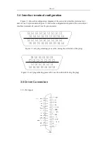
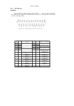
Страница 21: ...guration diagram of the servo driver interface terminal cn2 and cn2 is a 26 pin connector 18 16 14 12 10 8 6 4 2 17 15 13 11 9 7 5 3 1 36 35 34 33 32 31 30 29 28 27 26 25 24 23 22 21 20 19 Figure 3 1 cn1 plug soldering piece s361 facing the solder tab of the plug 13 12 11 10 9 8 7 6 5 4 3 2 1 26 25 24 23 22 21 20 19 18 17 16 15 14 Figure 3 2 cn2 plug soldering piece s261 see the solder tab facing ...

Страница 22: ... on counterclockwise rotation drive allows Fstp off counterclockwise rotation drive prohibition Note 1 For mechanical overrun when the switch is off the ccw direction torque remains at 0 Note 2 This function can be masked by parameter No 20 or forever Far away the switch is on CN1 10 Cw drive is prohibited RSTP P S Cw clockwise drive disable input terminal Rstp on Rotate the drive in a clockwise d...

Страница 23: ...s ready to output on Srdy off The main power supply is not connected or the AC servo drive unit has an alarm and the servo is ready to output off CN1 15 Servo alarm output ALM P S Servo alarm output terminal Alm on The servo unit has no alarm and the servo alarm output is on Alm off servo unit has alarm servo alarm output is off CN1 14 Position ing compl etion output COIN P Positioning completed o...

Страница 24: ...hapter 3 Interface Bz off the brake is cut off the brake is effective the motor is locked and cannot be operated The bz function is controlled internally by the drive CN1 25 Brake posit ive level BZ P S ...

Страница 25: ...wer supply 4 0V 17 5V Encoder power supply 5 5V Encoder power supply 18 5V 6 5V 19 W Incremental encoder feedback w 7 W Incremental encoder feedback w 20 V Incremental encoder feedback v 8 V Incremental encoder feedback v 21 U Incremental encoder feedback u 9 U Incremental encoder feedback u 22 Z Incremental encoder feedback z 10 Z Incremental encoder feedback z 23 B Incremental encoder feedback b...

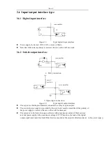
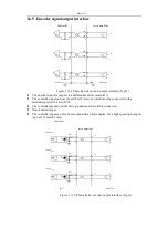
Страница 26: ...ut interface The output is a Darlington transistor connected to a relay or optocoupler The external power supply is provided by the user but it must be noted that if the polarity of the power supply is reversed the servo drive will be damaged The output is in the form of an open collector with a maximum current of 50mA and an external power supply with a maximum voltage of 25V Therefore the load o...

Страница 27: ...rder to correctly transmit the pulse amount data it is recommended to use a differential drive method In the differential drive mode the am26ls31 mc3487 or similar rs422 line driver is used With a single ended drive the operating frequency is reduced with a maximum pulse frequency of 200 kHz According to the pulse amount input circuit the driving current is 10 15mA and the condition that the maxim...

Страница 28: ...Chapter 3 Interface shows the pulse input timing and parameters When used In the case of 2 phase input its 4 octave pulse frequency is 500 kHz ...

Страница 29: ... 1μS 2 5μS trh 0 2μS 0 3μS trl 0 2μS 0 3μS ts 1μS 2 5μS tqck 8μS 10μS tqh 4μS 5μS tql 4μS 5μS tqrh 0 2μS 0 3μS tqrl 0 2μS 0 3μS tqs 1μS 2 5μS Pulse instruction form CCW CW Parameter setting Pulse train PULS symb ol SIGN 0 Command pulse symbol Ccw pulse train PULS Cw pulse train SIGN 1 Ccw pulse cw pulse Phase a pulse train PULS Phase b pulse train SIGN 2 2 phase command pulse ...

Страница 30: ...est pulse frequency 500kHz Figure 3 8 CCW pulse CW pulse input interface timing diagram highest pulse frequency 500kHz PULS SIGN Figure 3 9 2 phase command pulse input interface timing diagram highest pulse frequency 125kHz tqh tqck 90 10 tql tqs tqrh 90 tqrl tqs 10 tqrl tqrh CCW CW ...

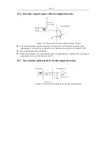
Страница 31: ...input interface Figure 3 10 a Analog Differential Input Interface type4 Figure 3 10 b Analog single ended input interface type4 Controller servoamplifier AS or AT 10k AGND AS or AT Controller servo amplifier AS or AT 10k AGND AS or AT ...

Страница 32: ... and the controller to the driver requires three wires to be connected In the single ended connection the analog ground and the input negative are connected on the driver side and the controller to the driver requires two wires to be connected Differential connection is superior to single ended connection which suppresses common mode interference The input voltage should not exceed the range of 10...

Страница 33: ...o the terminating resistor about 330ω The controller ground and the drive ground must be reliably connected Non isolated output The controller input can also be accepted with a photocoupler but a high speed optocoupler eg 6n137 must be used Controller Controller servo amplifier OA OA OB OB OZ OZ AM26LS32 GND AM26LS31 1N4148 220 1N4148 200 1N4148 220 OA OA OB OB OZ OZ servo amplifier A B Z 6N137 AM...

Страница 34: ...ears the output is on output is on otherwise the output is off output is off Non isolated output non isolated In the host computer the z phase signal pulse is usually narrow so please use a high speed optocoupler to receive for example 6n137 3 5 7 Servo motor photoelectric encoder input interface max 25V max 50mA servo CZ GND servo motor X X servo amplifier AM26LS32 X A B Z U V W Figure 3 13 Servo...

Страница 35: ...or has a resistance range of 40 200Ω and power of 100 50W The smaller the resistance is the larger the braking current is The greater the braking resistor power is the larger the braking energy is but the resistance is too small The drive is damaged The test method is to change the resistance from large to small until the drive no longer has an alarm The external braking resistor and internal brak...

Страница 36: ...00 100 9 Position proportional gain P 1 1000 40 1 s 10 Position feed forward gain P 0 100 0 11 Position feedforward filter cutoff frequency P 1 1200 300 Hz 12 Position command pulse frequency division molecule P 1 32767 1 13 Position command pulse frequency division denominator P 1 32767 1 14 Position command pulse input method P 0 2 0 15 Position command pulse direction is reversed P 0 1 0 16 Pos...

Страница 37: ... speed command direction is reversed S 0 1 0 45 Analog speed command zero offset compensation S 5000 5000 0 46 Analog speed command filter S 0 1000 300 Hz 47 Mechanical brake action setting when the motor is stopped P S T 0 200 0 10ms 48 Mechanical brake action setting when the motor is running P S T 0 200 50 10ms 49 Mechanical brake operating speed when the motor is running P S T 0 3000 100 r min...

Страница 38: ...T 1 31 1 61 Encoder output pulse division denominator P S T 1 31 1 62 Encoder output b pulse phase P S T 0 1 0 63 Encoder output z pulse phase P S T 0 1 0 64 Encoder output z pulse width P S T 0 15 0 68 Analog speed command dead zone 1 S 0 13000 0 mv 69 Analog speed command dead zone 2 S 13000 0 0 mv ...

Страница 39: ... password is 315 The model code password is 385 0 9999 1 Model code Corresponds to the same series of drivers and motors of different power levels The default values of the parameters corresponding to different model codes are different When using the function of restoring default parameters the correctness of this parameter must be guaranteed When the eeprom alarm No 20 appears after repairing yo...

Страница 40: ...nd pulse accumulation amount is 5 digits high 5 The display position deviation is 5 digits lower 6 The display position deviation is 5 digits high 7 Display motor torque 8 display motor current 9 display linear speed 10 display control mode 11 Display the position command pulse frequency 12 Display speed command 13 Display a torque command 14 Display the absolute position of the rotor in one revol...

Страница 41: ... 2 sc1 off sc2 on internal speed 3 sc1 on sc2 on internal speed 4 Test run control mode speed command input from the keyboard used to test the drive and motor Jog control mode that is jog mode after entering jog operation press key and hold the motor runs at jog speed release button motor stops keep zero speed press key and hold motor press jog speed Run in reverse release the button the motor sto...

Страница 42: ...t Set the integral time constant of the speed loop regulator The smaller the setting value the faster the integration speed the stronger the system resistance deviation that is the greater the stiffness but it is too small to produce overshoot 1 1000ms ...

Страница 43: ... case A higher speed response is required and the set value can be appropriately increased 20 500 9 Position proportional gain Set the proportional gain of the position loop regulator The larger the setting value the higher the gain the greater the stiffness and the smaller the position lag amount under the same frequency command pulse condition However too large a value may cause oscillation or o...

Страница 44: ...system C 2500 Example When the input command pulse is 6000 the servo motor rotates 1 circle Then the parameter PA12 is set to 5 and PA13 is set to 3 The recommended range of electronic gear ratio is See parameter PA12 Set the input form of the position command pulse The parameter is set to one of three input methods CCW is viewed from the axial direction of the servo motor and rotates counterclock...

Страница 45: ...sition out of tolerance alarm detection range In the position control mode when the count value of the position devia tion counter exceeds When this parameter is used the servo drive gives a position error alarm 18 Location error Invalid SET AS 0 The position over tolerance alarm detection is valid 1 The position error detection is invalid and the detection position error is stopped 0 1 19 Positio...

Страница 46: ...speed 1 The speed command is taken from an external analog input The drive with analog function can be set to 0 or 1 without A drive with analog function can only be set to 0 0 1 23 Maximum speed limit system Set the maximum speed limit of the servo motor Independent of the direction of rotation If the set value exceeds the rated speed the actual maximum speed limit is rated speed 24 Internal spee...

Страница 47: ...tected In the case of PA31 9 when the motor torque is PA30 duration PA31 In the case the drive alarms the alarm number is Err 29 and the motor stops After the alarm is generated the drive must be powered back on to clear the alarm 1 300 31 User torque Alarm detection time User torque overload detection time in milliseconds Detection time parameter value 0 1 When set to 0 9 the user torque overload...

Страница 48: ...e system 36 External CCW Torque limit Set the external torque limit value of the servo motor in the CCW direction The set value is a percentage of the rated torque for example set to the rated torque 1 time the setting value is 100 This limit is only available when the CCW torque limit input terminal FIL is ON The system is effective When the limit is valid the actual torque limit is the maximum o...

Страница 49: ...eristics are linear Only for speed control mode position control mode is invalid If the drive is used in combination with an external position loop this parameter should be set to 0 42 S type acceleration and deceleration Time constant Set the S type acceleration deceleration curve part of the time to make the motor start and stop smoothly 43 Analog speed Command input in crease beneficial Set the...

Страница 50: ...the mechanical brake during motor operation The speed value of the output terminal BRK from ON to OFF The actual operating time is required for PA48 or motor deceleration to PA49 value Time the minimum of the two See Figure 7 5 for the timing 50 Torque control Speed limit During torque control the motor running speed is limited to this parameter It can prevent overspeed in light loads 51 Dynamic e...

Страница 51: ...le ALRS alarm clearing FSTP CCW driver is prohibited RSTP CW drive is disabled 54 High 4 bit input Terminal forcing ON control word Set the input terminal to be inverted Terminals that are not inverted when the switch is closed Effective the switch is invalid when it is open the reversed terminal is not when the switch is closed Effective effective when the switch is off Expressed as a 4 bit binar...

Страница 52: ... driver is prohibited RSTP CW drive is disabled 56 High 4 bit input Terminal counter con trol Word Set the input terminal to be inverted Terminals that are not inverted when the switch is closed Effective the switch is invalid when it is open the reversed terminal is not when the switch is closed Effective effective when the switch is off It is represented by a 4 digit binary number This bit is 0 ...

Страница 53: ...y 1 means negated Binary generation The input terminals of the table are as follows 3 2 1 0 BRK ALM SRDY SRDY The servo is ready ALM servo alarm COIN Positioning completed speed reached BRK Mechanical brake release 58 Io input terminal Debounce time constant Debounce filtering time on the input terminal The smaller the value the faster the terminal input response The higher the value the better th...

Страница 54: ...er of encoder lines out put only smaller than the motor encoder The number of lines is convenient for connection with the host de vice Especially in the upper device receiving When the maximum frequency of the pulse is limited the encoder pulse can be reduced after the frequency division setting frequency If the motor encoder uses a C line encoder the output encoder line number for For example if ...

Страница 55: ... phase Parameter meaning 0 in phase 1 inversion This parameter can adjust the phase relationship between the B phase signal and the A phase signal 0 1 63 Encoder output Z pulse phase Parameter meaning 0 in phase 1 inversion 0 1 ...

Страница 56: ...r device cannot capture the narrow Z pulse it can enter the Z pulse Line width parameter meaning 0 15 68 Analog speed Dead zone 1 The input voltage is between dead zone 2 parameter 69 dead zone 1 parameter 68 The time instruction is forced to 0 0 ...

Страница 57: ...tion counter exceeds 230 9 Encoder failure Encoder signal error 10 Control power supply undervoltage Low control power 11 Ipm module failure Ipm intelligent module failure 12 Overcurrent Motor current is too large 13 Overload Servo drive and motor overload instantaneous overheating 14 Brake failure Brake circuit failure 15 Encoder count error Encoder count is abnormal 16 Motor thermal overload Mot...

Страница 58: ...Chapter 4 Parameters 32 Encoder uvw signal is illegal coding Uvw signal has full high level or full low level 33 Provincial line encoder signal error No high impedance state in power up sequence ...

Страница 59: ... too large Increase the acceleration deceleration time constant The input electronic gear ratio is too large Set it up correctly The encoder is faulty Replace the servo motor Defective encoder cable Replace the encoder cable The servo system is unstable causing overshoot Reset the relevant gain If the gain cannot be set to a suitable value reduce the load moment of inertia ratio Appears when the m...

Страница 60: ...Replace the servo drive The brake circuit capacity is not enough Reduce the start and stop frequency Increase the acceleration deceleratio n time constant Reduce the torque limit value Reduce the load inertia Replace high power drives and motors 3 Main circuit undervoltag e Appears when the main power is turned on The board is faulty The power supply is damaged The soft start circuit is faulty The...

Страница 61: ...o small Increase the position error detection range The position proportional gain is too small Increase the gain Insufficient torque Check the torque limit value Reduce the load capacity Replace high power drives and motors The command pulse frequency is too high Reduce the frequency Encoder zero point change Re adjust the encoder zero 5 Motor overheating Appears when the control power is turned ...

Страница 62: ...lt Appears during motor operation The motor is mechanically stuck Check the load mechanical part The load is too large Reduce the load Replace high power drives and motors 7 Drive prohibited abnormal Ccw cw drive disable input terminals disconnect Check the wiring ...

Страница 63: ...The input control power is low Check the control power Defective internal connector of the drive The switching power supply is abnormal The chip is damaged Replace the drive Check the connector Check the switching power supply 11 Ipm module failure Switch on control Appears when power The board is faulty Replace the servo drive Appears during motor operation The supply voltage is low overheat Chec...

Страница 64: ...n deceleration time Reduce the load inertia u v w have a phase break The encoder is wired incorrectly Check the wiring 14 Brake failure When the control power is turned on Now The board is faulty Replace the servo drive Appears during motor operation The brake resistor wiring is broken Rewire The brake transistor is damaged The internal braking resistor is damaged Replace the servo drive The brake...

Страница 65: ...orrect Set the relevant parameters correctly Appears during motor operation Long term operation exceeds rated torque Check the load Reduce the start and stop frequency Reduce the torque limit value Replace high power drives and motors Poor mechanical transmission Check the mechanical part 17 Brake average power overload The input AC power is high Check the power supply voltage Regenerative braking...

Страница 66: ...ce the servo drive After repair you must reset the drive model parameter pa1 and then restore the default parameters 21 U4 error The chip or board is damaged Replace the servo drive 23 U6 chip error The chip or board is damaged The current sensor is damaged Replace the servo drive ...

Страница 67: ...ace circuit 31 Encoder Uvw signal error The encoder uvw signal is corrupted The encoder z signal is corrupted Bad cable Poor cable shielding The shielded ground wire is not connected The encoder interface circuit is faulty Replace the encoder Check the encoder interface circuit 32 Encoder Ivw signal illegal coding The encoder uvw signal is corrupted Bad cable Poor cable shielding The shielded grou...

Страница 68: ...determine the meaning key has the meaning of exit cancel key means increase decrease the serial number or value size If the keys are pressed and held there is a repeating effect and the longer the holding time the higher the repetition rate If the decimal point of the 6 digit tube or the rightmost digit tube is flashing an alarm has occurred POWER indicator Lit indicates that the main power has be...

Страница 69: ...he mode with the and keys Press the Enter key to enter the selection In the second layer of the fixed mode press the key to return to the first layer from the second layer Monitoring method parameter settings Parameter management Speed trial run JOG operation Automatic gain adjustment Encoder zeroing Open loop operation Tier 1 Level 2 ...

Страница 70: ...se Position deviation high 5 bits 100000 pulses Motor torque Motor current A Linear speed m min Current control method Position command pulse frequency kHz Speed command r min Torque command Absolute position of the rotor in one revolution Rush Input terminal status Output terminal status Encoder input signal Operating status Alarm code Reserved Motor speed 1000r min Current position 1245806 pulse...

Страница 71: ...put electronic gear is amplified the minimum unit At 0 1 kHz the forward direction shows a positive number and the reverse direction shows a negative number Note 6 Indicates the effective value of the phase current The calculation method of the current I is Note 7 The absolute position of the rotor in one revolution indicates the position of the rotor relative to the stator in one revolution with ...

Страница 72: ...Increase or decrease the number 1 Press and hold the or key to increase or decrease the parameter continuously When the parameter value is modified the rightmost The LED digital tube on the side is lit with a decimal point Press Enter to confirm that the modified value is valid At this time the LED on the right is small The number is extinguished and the modified value will be immediately reflected in ...

Страница 73: ...e parameters in the parameter table to the parameters of the EEPROM In the zone the modified parameters will be used after power on The EE rd parameter reads which reads the data of the parameter area of the EEPROM into the parameter table This process is It is automatically executed once at power on At the beginning the parameter values of the parameter table are the same as those in the parameter...

Страница 74: ...peration 6 7 Parameter Management Operation Block Diagram System power on EEPROM parameter area Parameters Table Parameter writing Parameters Table Parameters Table Parameters Table EEPROM parameter area EEPROM parameter area EEPROM parameter area default value Parameter default Figure 6 8 Parameter Management Operation Meaning ...

Страница 75: ... value Enter PA45 or PA39 and save it to the EEPROM Select AU in the first layer and press Enter to enter Zero operation mode After auto zeroing the user can continue to modify PA45 or PA39 for manual zero adjust ment Press and hold for 3 seconds Successful operation Speed analog Torque analog operation failed In operation Figure 6 9 Analog automatic zeroing operation block diagram ...

Страница 76: ...y the control is turned on The power supply of the circuit the servo ready signal SRDY OFF 3 After the main circuit power is turned on the delay is about 1 5 seconds the servo ready signal SRDY is ON and the servo can be accepted at this time Service enable SON signal detection of servo enable is valid base circuit is on motor is energized is running status The servo enable is detected to be inval...

Страница 77: ...y the control is turned on The power supply of the circuit the servo ready signal SRDY OFF 3 After the main circuit power is turned on the delay is about 1 5 seconds the servo ready signal SRDY is ON and the servo can be accepted at this time Service enable SON signal detection of servo enable is valid base circuit is on motor is energized is running status The servo enable is detected to be inval...

Страница 78: ...al brake release BRK Mechanical brake release BRK 0FF brake hold 0FF brake hold 0FF brake hold No power free No power free No power free ON brake release ON brake release PA47 parameter setting Figure 7 5 Mechanical brake action sequence when the motor is stopped motor speed 30r min Motor speed r min 7 6 Mechanical brake action timing when the motor is running ...

Страница 79: ...rnal torque limit parameters PA34 PA35 to reduce the motor High speed parameter PA23 method The start stop frequency allowed by the servo motor varies with load conditions running time and other factors Gener al load inertia The number is less than 5 times When used under large load inertia it may happen that the main circuit overvoltage or braking is different during deceleration Often you can us...

Страница 80: ... l Control voltage terminals r t are connected to single phase AC 220V l Encoder signal connector CN2 is connected to the servo motor l Control signal connector CN1 Connect as shown Figure 7 7 Test run wiring diagram 3 JOG operation l Turn on the control circuit power supply the main circuit power supply is temporarily not connected the dis play of the drive is lit if an alarm occurs Please check ...

Страница 81: ...tor runs at JOG speed re lease button Key the motor stops keeps zero speed press key and hold the motor runs in reverse direction at JOG speed release the button The motor stops and keeps at zero speed The JOG speed is set by parameter PA21 and the default is 120r min Figure 7 8 JOG operation block diagram l If the external control servo enable SON is inconvenient you can set the parameter PA53 to...

Страница 82: ... to R S T terminals l Control voltage terminals r t are connected to single phase AC 220V l Encoder signal connector CN2 is connected to the servo motor l Control signal connector CN1 Connect as shown 2 operating l Turn on the control circuit power and main power The display has a display and the POWER indicator lights up l Set the parameter values ...

Страница 83: ...le user settings 1 PA13 Electronic gear denominator user settings 1 PA19 Position command smoothing filter 0 0 PA20 Drive inhibit input is invalid 1 0 After the alarm and any abnormal conditions the servo enable SON is turned on the RUN indicator is lit the slave controller Send the low frequency pulse signal to the drive to make the motor run at low speed ...

Страница 84: ...ber of input pulses and the number of revolutions Input pulse number Number of motor revolutions Electronic gear mol ecule PA12 Electronic gear Sub PA13 Pules PA12 PA13 10000 1 1 1 5000 1 2 1 3000 1 10 3 800 1 25 2 20000 1 1 2 1000 2 3 20 3 4000 3 30 4 Table 7 2 Relationship between input pulse frequency and rotation speed Input pulse frequency Hz Motor speed r min Electronic gear mol ecule PA12 E...

Страница 85: ...onnector CN2 is connected to the servo motor l Control signal connector CN1 is connected as shown l If only speed control is used it is not necessary to connect the encoder output signal if the external controller is a position controller Need to connect the encoder output signal Figure 7 11 Simple wiring diagram of speed control mode 2 Operation l Turn on the control circuit power and main power ...

Страница 86: ...servo enable SON turns ON and the RUN indicator lights l Add an adjustable DC voltage to the analog speed input port gradually increase this voltage from 0 to ensure motor rotation The speed changes accordingly with the command when a negative voltage is applied the motor should be reversed l Close the zero speed clamp switch ZEROSPD the motor should stop at zero speed l If the given analog comman...

Страница 87: ......

Страница 88: ...rol voltage terminals r t are connected to single phase AC 220V l Encoder signal connector CN2 is connected to the servo motor l Control signal connector CN1 Connect as shown 7 12 Simple wiring diagram of torque control mode 2 Operation l Turn on the control circuit power and main power the display has a display and the POWER indicator lights up l Set the parameter values ...

Страница 89: ...Chapter 7 Running 7 9 2 Operation l Set the parameter values ...

Страница 90: ... Note When switching electronic gears the timing of Figure 7 14 must be met before and after the change point of input INH Less 10ms don t pulse Figure 7 14 Dynamic Electronic Gear Switching Timing 7 10 Input terminal switching control mode The input terminal switching control mode function means that the two control modes are implemented by ON OFF of one input terminal When switching you can swit...

Страница 91: ...from happening in some cases the motor load is abnormally increased which may damage some machines The device is designed with a user torque overload alarm function When the function is valid the drive system detects the motor torque when It is found that the torque is higher than the given parameter value and after a period of time the drive alarms the alarm number is Err 29 and the motor stops t...

Страница 92: ...Chapter 8 Specifications 8 1 Servo drive model 8 2 Servo drive size Size mm A B 2A 3A 152 77 5A 200 108 Figure 1 1 Driver Dimensions ...

Страница 93: ...orque limit 8cw torque limit Control output 1 servo ready output 2 servo alarm output 3 positioning completion output speed arrival output 4 mechanical brake output Position control Input 1 pulse symbol 2ccw pulse cw pulse 3 two phase a b orthogonal pulse Electronic gear 1 32767 1 32767 Feedback pulse 2500 lines turn speed control 4 internal speeds Acceleration and deceleration Parameter setting 1...

Страница 94: ... If you need to modify the model code or need to restore the factory default parameter combination please refer to Section 7 13 1 Implementation At present the motors that can be adapted to the manufacturers are motor manufacturers such as Huada and MiG 8 4 1 Huada MiG AC servo motor adaptation Table 8 2 Huada MiG AC servo motor adapter table motor model Torqu e N m Rotati ng speed rpm pow er kW H...

Страница 95: ...0 91 100 130ST M07720 7 7 2000 1 5 42 47 0 130ST M07725 7 7 2500 2 0 92 101 130ST M07730 7 7 3000 2 3 48 1 130ST M10010 10 0 1000 1 0 71 93 130ST M10015 10 0 1500 1 5 43 49 2 72 94 102 130ST M10025 10 0 2500 2 5 50 3 95 103 130ST M12020 12 0 2000 2 4 52 11 130ST M15015 15 0 1500 2 3 51 4 96 104 130ST M15025 15 0 2500 3 8 5 105 150ST M12030 12 0 3000 3 6 6 150ST M15025 15 0 2500 3 8 7 150ST M18020 ...

Страница 96: ...e power input 1 Motor housing ground terminal 8 6 2 Brake Terminal symbol Terminal number Terminal description DC 1 Brake power supply is DC power supply Non polar access requirements DC 2 3 Motor housing ground Frame number 130 mm s basic type a Optional model 1 b Alternative model 2 l drive adaptation voltage ac220v Rated torque 0 1 N m n Do not configure z configure the power off brake f standa...

Страница 97: ...se output B 8 Z 6 Encoder z phase output Z 9 U 10 Encoder u phase output U 13 V 11 Encoder v phase output V 14 W 12 Encoder w phase output W 15 PE 1 Encoder housing 8 6 4 Incremental line encoder Terminal symbol Terminal number Terminal description 5V 2 Encoder 5v power input 0V 3 A 4 Encoder a phase output A 7 B 5 Encoder b phase output B 8 Z 6 Encoder z phase output Z 9 PE 1 Encoder housing ...

Страница 98: ... 3000 3000 3000 Rated torque N m 0 637 1 27 1 91 Peak torque N m 1 911 3 8 5 73 Rotor inertia kg m2 0 17 10 4 0 302 10 4 0 438 10 4 Encoder line number ppr 2500 Motor insulation grade ClassB 130 Protection level IP64 Use environment Ambient temperature 20 C 50 C Ambient humidity relative humidity 90 without frosting conditions Encoder line sequence Socket number 1 2 3 4 5 6 7 8 9 10 11 12 13 14 15...

Страница 99: ...00 2500 Rated torque N m 1 27 2 39 3 5 4 0 Peak torque N m 3 8 7 1 10 5 12 Rotor inertia kg m2 1 05 10 4 1 82 10 4 2 63 10 4 2 97 10 4 Encoder line number ppr 2500 Motor insulation grade ClassB 130 Protection level IP65 Use environment Ambient temperature 20 C 50 C Ambient humidity relative humidity 90 without frosting conditions Socket number 1 2 3 4 5 6 7 8 9 10 11 12 13 14 15 parameters Lead de...

Страница 100: ... N m 7 1 10 5 12 0 Rotor inertia kg m2 2 45 10 4 3 4 10 4 3 7 10 4 Encoder line number ppr 2500 Motor insulation grade ClassB 130 Protection level IP65 Use environment Ambient temperature 20 C 50 C Ambient humidity relative humidity 90 without frosting conditions A A 0 0 03 Socket number 1 2 3 4 5 6 7 8 9 10 11 12 13 14 15 Lead PE 5V 0V B Z U Z U V A B W 86 0 3 Ø113 A A 3 25 3 35 L Ø100 4 Ø6 5 130...

Страница 101: ...ent a 2 5 3 5 5 0 5 0 6 0 4 5 6 0 Rated speed rpm 3000 2000 3000 2000 3000 2000 3000 Rated torque N m 2 0 4 0 4 0 5 0 5 0 6 0 6 0 Peak torque N m 6 0 12 12 15 15 18 18 Rotor inertia kg m2 0 31 10 3 0 54 10 3 0 54 10 3 0 71 10 3 0 63 10 3 0 76 10 3 0 76 10 3 Encoder line number ppr 2500 Motor insulation grade ClassB 130 Protection level IP65 Use environment Ambient temperature 20 C 50 C Ambient hum...

Страница 102: ...6 0 6 0 7 5 4 5 6 0 10 9 5 13 5 Rated speed rpm 2500 2500 2500 2000 2500 1000 1500 2500 1500 2500 Rated torque N m 4 0 5 0 6 0 7 7 7 7 10 10 10 15 15 Peak torque N m 12 15 18 22 22 20 25 25 30 30 Rotor inertia kg m 2 0 85 10 3 1 06 10 3 1 26 10 3 1 58 10 3 1 53 10 3 1 94 10 3 1 94 10 3 1 94 10 3 2 77 10 3 2 77 10 3 Encoder line number 2500 Motor insulation grade ClassB 130 Protection level IP65 Us...

Страница 103: ...d line current a 16 5 16 5 20 5 20 5 Rated speed rpm 2500 2000 2000 2000 Rated torque N m 15 0 18 0 23 0 27 0 Peak torque N m 45 0 54 0 69 0 81 0 Rotor inertia kg m2 6 15 10 3 6 33 10 3 8 94 10 3 11 19 10 3 Encoder line number ppr 2500 Motor insulation grade ClassB 130 Protection level IP65 Use environment Ambient temperature 20 C 50 C Ambient humidity relative humidity 90 without frosting conditi...

Страница 104: ...rrent a 10 5 12 16 16 19 32 Rated speed rpm 1500 1500 2000 1500 1500 1500 Rated torque N m 17 2 19 21 5 27 35 48 Peak torque N m 43 47 53 67 70 96 Rotor inertia kg m2 3 4 10 3 3 8 10 3 4 7 10 3 6 1 10 3 8 6 10 3 9 5 10 3 Encoder line number ppr 2500 Motor insulation grade ClassB 130 Protection level IP65 Use environment Ambient temperature 20 C 50 C Ambient humidity relative humidity 90 without fr...

Отзывы: