BUILD THE AILERONS
❏ ❏
1. If you have built flaps, remove them from the
right wing panel. Use a razor saw to separate the
aileron from the wing by cutting between the LE of
the aileron and the TE of the wing. Refer to the plan
to find the location of this gap and poke a pin through
the sheeting to verify you have found the gap. Use
the razor saw to cut the ends of the aileron from the
wing along the holes you poked in the top sheeting.
❏ ❏
2. Sand the sheeting and the
rib stubs on the
wing even with the TE. Glue a piece of leftover 3/32”
[2.4mm] balsa to the wing tip rib. Sand it to the shape
of the wing.
❏ ❏
3. Sand the sheeting and the
rib stubs on the
aileron even with the LE and the tips. Glue the die-cut
1/8” [3.2mm] balsa
aileron leading edge (W17A)
to
the front of the aileron. Sand the leading edge flush with
the ends and top and bottom of the aileron.
❏ ❏
4. Use the
straightedge and T-pin technique to
mark a centerline on the wing TE and the aileron LE.
Cut the hinge slots where shown on the plan. Test fit
the aileron to the wing with the hinges. Adjust any
hinge slots if necessary so the aileron and wing
align. Sand the tip of the aileron so there is about a
1/16” [1.6mm] gap between the end of the aileron
and the wing tip.
❏ ❏
5. Bevel the leading edge of the aileron to a “V”
using the centerline as a guide. The bevel must
permit the full amount of aileron throw as specified
on page 62, plus a bit extra to prevent servo binding.
❏ ❏
6. Replace the flap onto the wing. Adjust the
root of the aileron and the tip of the flap so there is
approximately a 3/32” [2.4mm] gap between them.
❏
7. Return to the first step and build the aileron on
the left wing panel the same way.
MOUNT THE FLAP AND AILERON SERVOS
❏ ❏
1. Cut the openings in the bottom of the wing
sheeting for the die-cut 1/16” [1.6mm] plywood
aileron and flap servo hatch covers
(if you’re
building flaps). Start by cutting a smaller opening at
the location indicated on the plan. Carefully enlarge
the hatch openings using a fresh #11 blade and a
straightedge until the hatch covers fit.
Hint:
As you
zero-in on the final shape of the hatch
openings, use the hatch covers themselves as a
template to cut the openings.
❏ ❏
2. Drill 1/16” [1.6mm] holes through the punch
marks in the servo hatch covers. Place the hatch
covers on the rails in the hatches and drill 1/16”
[1.6mm] holes through the hatch covers into the rails.
❏ ❏
3. Enlarge the holes
in the hatch covers only
with a 3/32” [2.4mm] drill bit.
Countersink the holes
for the #2 x 3/8” [9.5mm] flat head screws with a
countersink or other pointed tool. Test fit the hatch
covers to the rails with the screws. If necessary,
remove the hatch covers and sand the sides of the
hatch covers so they align with the edges of the
hatch openings. Remove the hatch and harden the
screw holes with some thin CA.
Note:
Though the
hatch covers are 1/16” [1.6mm] thick and the wing
sheeting is 3/32” [2.4mm] thick, by the time you sand
the wing sheeting smooth it will be the same height
as the hatch covers. If not, you can raise the hatch
covers by placing thin shims made from 1/64”
[0.4mm] plywood or thin cardstock on top of the rails.
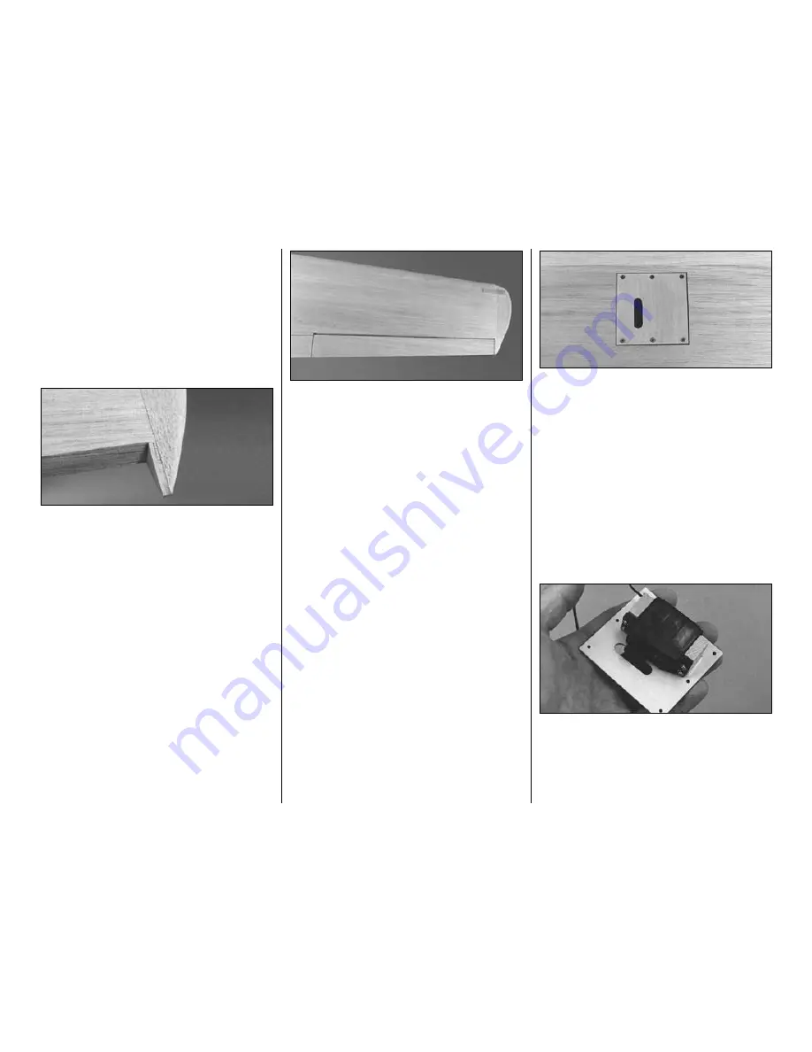
Use this photo for the next two steps.
❏ ❏
4. Mount each servo to two 5/16” x 3/4” x 7/8”
[7.9 x 19 x 22.2mm]
servo mount blocks
with the
screws, grommets and eyelets included with your
servos. Remove the screws, harden the screw holes
with some thin CA and then reinstall the servo. Be
sure that the servo is aligned so that the servo arm
is in the center of the cutout.
-32-
Содержание T-34B MENTOR
Страница 7: ...7 DIE CUT PATTERNS...


