TOHATSU BFT 250A Скачать руководство пользователя страница 107

4-15

dummyhead

dummyhead

TROUBLESHOOTING

FUSE/ELECTRIC POWER LINE 

TROUBLESHOOTING

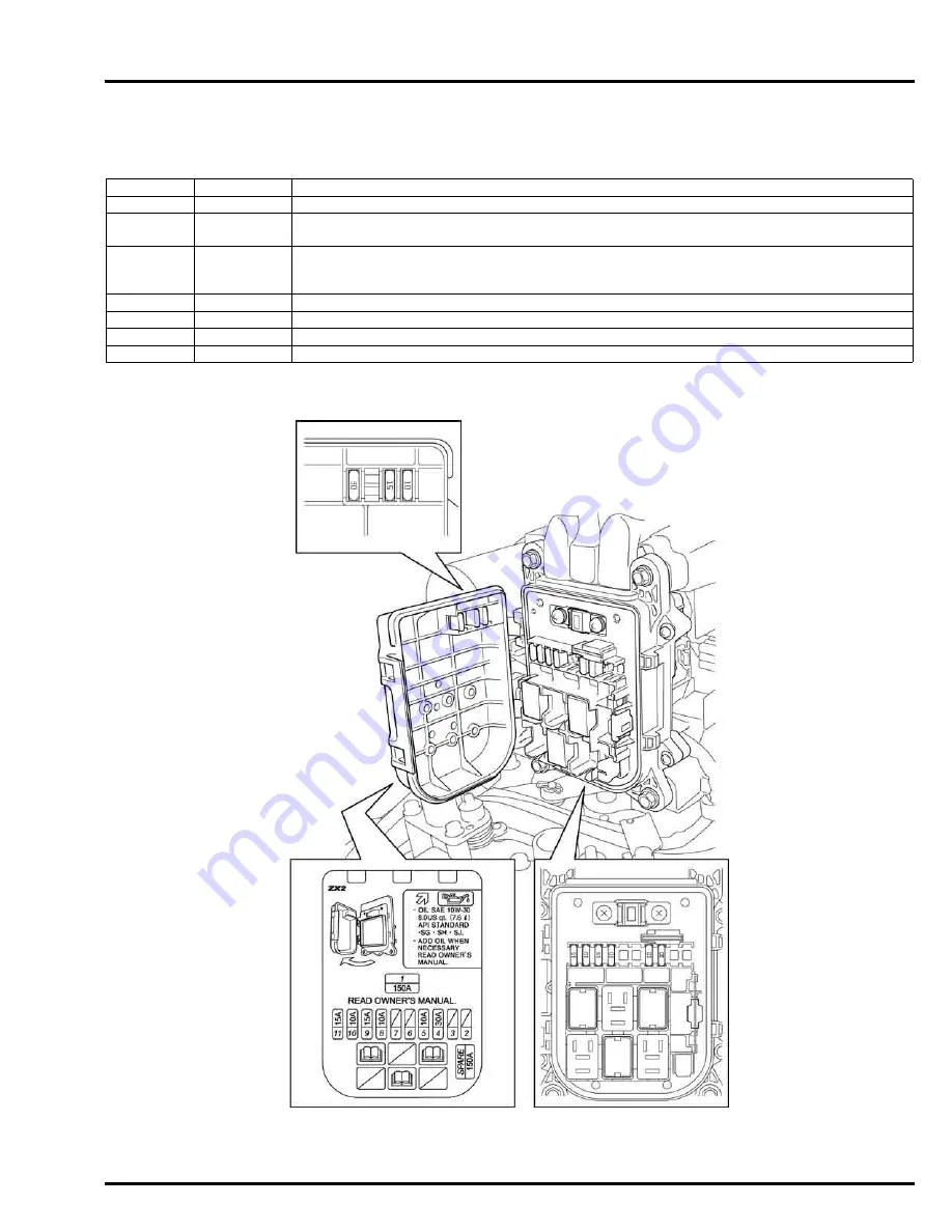
FUSE CONNECTION TABLE

Fuse No.

Amps.

Component(s) or Circuit(s) Protected

1

150 A

Alternator (Output terminal) 

4

30  A

ECM (Power supply), Fuel injector, Alternator, DLC, O

2

 sensor heater, IAB control solenoid valve, 

Direct ignition coil, Relay (Included in the junction box: Main relay, Starter relay, Fuel pump relay)

5

10  A

Alternator (Input terminal), Combination switch, Power tilt relay, Warning buzzer, Oil indicator 

light, Overheat indicator light, MIL, Alternator indicator light, tachometer, Trim meter, Hour meter, 

Volt meter, Relay (Included in the junction box: Main relay, Starter relay)

8

10 A

Fuel pump (High pressure side)

9

15 A

ECM (Power supply), Fuel injector 

10

10 A

Alternator, O

2

 sensor heater, IAB control solenoid valve, DLC

11

15 A

Direct ignition coil

Содержание BFT 250A

Страница 1: ...OB No 61ZX210 14 01 NB OB No 61ZX210 14 01 NB Printed in Japan BFT 250A BFT250A BFT250A BFT250AEUR_Cover_131219 indd 1 14 1 7 3 08 40 PM...

Страница 2: ...ce have to be done properly by service technicians with fundamental knowledge and skills This manual is utilized so that our customers can always use their outboard motor with full satisfaction As thi...

Страница 3: ...manuel est pr vu pour que nos clients puissent toujours utiliser leur moteur hors bord pour leur plus grande satisfaction Ce document contient des informations provenant du manuel de r paration des m...

Страница 4: ...manual permitir a nuestros clientes utilizar siempre su motor fuera de borda con plena satisfacci n Debido a que este documento contiene informaci n extra a del manual de servicio de Honda Motor el mi...

Страница 5: ...rt werden Dieses Handbuch wird genutzt damit unsere Kunden ihren Au enbordmotor zur vollen Zufriedenheit benutzen k nnen Da dieses Dokument Information des Honda Motor Service Handbuchs enth lt findet...

Страница 6: ...ring appropriate clothing and using safety equipment When performing any service task be especially careful of the following Read all of the instructions before you begin and make sure you have the to...

Страница 7: ...OVER LOCK 6 CHARGING SYSTEM 7 IGNITION SYSTEM 8 STARTING SYSTEM 9 OTHER ELECTRICAL 10 COOLING SYSTEM 11 LUBRICATION SYSTEM 12 ENGINE REMOVAL INSTALLATION 13 CYLINDER HEAD 14 CYLINDER BLOCK 15 GEAR CAS...

Страница 8: ...e it is not practical or possible to warn you about all the hazards associated with servicing these products You must use your own good judgement Honda Motor Co Ltd SERVICE PUBLICATION OFFICE Date of...

Страница 9: ...e hole Use only metric tools when servicing this unit Metric bolts nuts and screws are not interchangeable with non metric fasteners The use of incorrect tools and fasteners will damage the unit SYMBO...

Страница 10: ...e Coolant Temperature ECM Engine Control Module EMT Exhaust Manifold Temperature EOP Engine Oil Pressure EX Exhaust F Front or Forward GND Ground HO2S Heated Oxygen sensor IAB Intake Air Bypass IAC Id...

Страница 11: ...1 1 1 dummytext 1 GENERAL INFORMATION SERIAL NUMBER LOCATION 1 2 SPECIFICATIONS 1 2 DIMENSIONAL DRAWING 1 4...

Страница 12: ...E PRODUCT IDENTIFICATION NUMBER ENGINE SERIAL NUMBER Model BF250A Type LA XA XCA XXA XXCA Shaft Length type L XL XL XXL XXL Counter Rotation Remote control Power Trim Tilt Tachometer Trim meter XL Ext...

Страница 13: ...ystem Programmed fuel injection Fuel injection system Electronic control Fuel injection nozzle Multi point type Fuel Unleaded gasoline with a pump octane rating of 86 or higher Fuel pump Electric and...

Страница 14: ...ON DIMENSIONAL DRAWING Transom H T LA type 1 760 mm 69 3 in 508 mm 20 0 in XA and XCA types 1 887 mm 74 3 in 635 mm 25 0 in XXA and XXCA types 2 014 mm 79 3 in 762 mm 30 0 in 920 mm 36 2 in 625 mm 24...

Страница 15: ...1 5 dummyhead dummyhead GENERAL INFORMATION 482 mm 19 0 in 629 5 mm 24 8 in 482 mm 19 0 in 30 30 93 7 mm 3 7 in 75 8 mm 3 0 in 1 015 mm 40 0 in 68 12...

Страница 16: ...Propeller shaft 4 mm 0 2 in ANSI INV S 16 32 x 15T x 30 M18 x 1 5 mm 16 86 16 93 mm 0 664 0 667 in 24 8 24 9 mm 0 976 0 980 in 29 9 30 2 mm 1 177 1 189 in 30 31 7 mm 0 3 in 28 5 mm 1 12 in 57 0 58 0 m...

Страница 17: ...1 2 dummytext 2 SERVICE INFORMATION MAINTENANCE STANDARDS 2 2 ENGINE FRAME TORQUE VALUES 2 4 STANDARD TORQUE VALUES 2 7 TOOLS 2 8 LUBRICATION SEAL POINT 2 15 CABLE HARNESS ROUTING 2 19 TUBE ROUTING 2...

Страница 18: ...0 067 0 0026 EX 0 026 0 077 0 0010 0 0030 0 077 0 0030 Pistons Skirt O D 88 974 88 984 3 5029 3 5033 88 964 3 5025 Piston to cylinder clearance 0 016 0 041 0 0006 0 0016 0 080 0 0032 Pin bore I D 21 9...

Страница 19: ...0 20 0 008 Outer rotor to oil pump body clearance 0 10 0 18 0 004 0 007 0 20 0 008 Outer rotor to oil body side clearance 0 02 0 07 0 001 0 003 0 12 0 005 Oil pressure 117 176 kPa 1 2 1 8 kgf cm2 17 2...

Страница 20: ...ilt assembly Lower chamber blow pressure 8 826 11 768 kPa 90 120 kgf cm2 1 280 1 707 psi Upper chamber blow pressure 3 923 7 355 kPa 40 75 kgf cm2 569 1 067 psi Power tilt motor assembly Brush length...

Страница 21: ...pressure side PT 1 8 8 0 0 82 5 9 EOP switch High pressure side M10 x 1 25 22 2 2 16 MAP sensor M5 x 0 8 3 4 0 35 2 5 IAT sensor M12 x 1 5 18 1 8 13 EBT sensor M10 x 1 25 12 1 2 9 EMT sensor M10 x 1...

Страница 22: ...rew M5 x 0 8 1 0 0 1 0 7 Item Thread Dia and pitch Torque values Remarks mm in N m kgf m lbf ft Drain plug cover special screw M6 x 1 0 6 4 0 65 4 7 Lower rubber mount nut M14 x 1 5 103 10 5 76 Upper...

Страница 23: ...screw 3 4 0 35 2 5 Water separator cover screw washer M5 x 0 8 3 4 0 35 2 5 Starter rear bracket screw M5 x 0 8 2 5 0 25 1 8 Starter rear bracket bolt screw M5 x 0 8 5 0 0 51 3 7 Power tilt relay mou...

Страница 24: ...Accessory package 246 NWY KACC246 Digital multimeter FLU 88 Idle speed electrical testing Engine oil pressure gauge kit Engine oil pressure gauge MT37A MT37AH Cylinder leak oil pressure testing inspec...

Страница 25: ...evel gauge 07401 0010000 Fuel pressure gauge 0 100 psi 07406 004000B Remover weight 07936 371020A or 07936 3710200 Valve guide driver 5 35 x 9 7 mm 07742 0010100 Attachment 32 x 35 mm 07746 0010100 At...

Страница 26: ...Attachment 25 mm I D 07746 0030200 Puller adapter 07APF ZY3A200 Pilot 20 mm 07746 0040500 Pilot 35 mm 07746 0040800 Pilot 30 mm 07746 0040700 Pilot 25 mm 07746 0040600 Pilot 14 mm 07746 0041200 Pilot...

Страница 27: ...r attachment 28 x 35 mm 07945 4150200 Bearing driver attachment 64 x 72 mm 07946 SB20000 Oil seal driver attachment 72 mm 07947 6340201 Driver 40 mm I D 07746 0030100 Oil seal driver 44 5 mm 07947 SB0...

Страница 28: ...A100 Holder handle 07JAB 001020A Pilot 28 mm 07JAD PH80400 Installer shaft 15 x 370 mm 07VMF KZ30200 Oil seal driver 65 mm 07JAD PL9A100 Belt tension gauge 07TGG 001000A or 07JGG 001010A Pressure gaug...

Страница 29: ...ssure gauge joint A 07SPJ ZW1010A Oil pressure gauge joint B 07SPJ ZW1020A Air adapter 070AJ 0010101 VTEC air stopper 070AJ 0030100 Oil seal driver attachment 80 x 96 mm 07ZAD PNA0100 Oil seal driver...

Страница 30: ...2 14 dummyhead dummyhead SERVICE INFORMATION Valve adjustment wrench 10 mm 07908 5900000 Engine hanger VSB02C000021 Attachment 27 5 x 44 mm 07948 9540000...

Страница 31: ...rface Connecting rod bearing crankshaft mating surface Main bearing crankshaft mating surface Thrust washer Cylinder sleeve inner surface Engine oil or silicone oil Shinetsu KF 96350 CS Fuel injector...

Страница 32: ...Water pump housing O ring O ring 65 4 x 2 4 mm Thrust bearing 85 x 110 x 4 mm Water pump O ring Pump liner inner surface Water tube seal ring inner wall Extension case grommet inner surface Water tub...

Страница 33: ...ion Remarks Marine grease water resistant urea based grease Shift rod A spline Shift shaft A water seal 14 x 26 x 8 mm lip and outer circumference Shift shaft A water seal contact surface and spline S...

Страница 34: ...THERS Material Location Remarks Marine grease water resistant urea based grease Drain plug rubber lip Alternator front bearing outer surface Alternator rear bearing inner surface Throttle cam Loctite...

Страница 35: ...TOR INDICATOR PANEL WIRE HARNESS 6P CONNECTOR HO2S 4P CONNECTOR SWITCH PANEL WIRE HARNESS 14P CONNECTOR ACG CABLE TERMINAL POWER TILT RELAY WIRE TERMINAL EMT SENSOR 2 2P CONNECTOR TRIM ANGLE SENSOR 3P...

Страница 36: ...RE TERMINAL INTERFACE 6P CONNECTOR ALTERNATOR 4P CONNECTOR SWITCH PANEL WIRE HARNESS 14P CONNECTOR DLC 4P INDICATOR PANEL WIRE HARNESS 6P CONNECTOR NEUTRAL SWITCH 2P CONNECTOR STARTER CABLE 1 HARNESS...

Страница 37: ...HARNESS GROUND TERMINALS POWER TILT RELAY CABLE GREEN TAPE YELLOW TAPE GREEN YELLOW RED ACG CABLE RED TAPE STARTER CABLE 1 MAIN WIRE HARNESS GROUND TERMINALS STOPPER POWER TILT RELAY GROUND TERMINALS...

Страница 38: ...WIRE HARNESS STARTER CABLE 1 STARTER CABLE 2 STARTER CABLE STARTER CABLE 1 NMEA INTERFACE WIRE Optional part NMEA INTERFACE WIRE Optional part SWITCH PANEL WIRE HARNESS SHIFT CONTROL CABLE STARTER CA...

Страница 39: ...SOR 3P CONNECTOR TP SENSOR 3P CONNECTOR No 1 DIRECT IGNITION COIL 3P CONNECTOR No 2 DIRECT IGNITION COIL 3P CONNECTOR No 3 DIRECT IGNITION COIL 3P CONNECTOR POWER TILT SWITCH 3P CONNECTOR THROTTLE CAB...

Страница 40: ...oint connector 1 as shown After installation check the main wire harness for twisting ACG CABLE TERMINAL STARTER CABLE 1 TERMINAL POWER TILT RELAY WIRE TERMINAL IAC VALVE 2P CONNECTOR TP SENSOR 3P CON...

Страница 41: ...h wire from the outside of the ECM bracket and check that the wire does not interfere with the ECM bracket CKP SENSOR 2P CONNECTOR ECM BRACKET HARNESS BAND CLIP POWER TILT SWITCH 3P CONNECTOR POWER TI...

Страница 42: ...N EMT SENSOR 2 2P CONNECTOR No 4 DIRECT IGNITION COIL 3P CONNECTOR No 5 DIRECT IGNITION COIL 3P CONNECTOR No 6 DIRECT IGNITION COIL 3P CONNECTOR WATER LEVEL SENSOR 2P CONNECTOR IAT SENSOR 2P CONNECTOR...

Страница 43: ...NGLE SENSOR WIRE POWER TILT RELAY CABLE POWER TILT MOTOR WIRE POWER TILT RELAY GROUND TERMINALS CABLE WIRE HARNESS CLIP HO2S 4P CONNECTOR POWER TILT RELAY 2P CONNECTOR POWER TILT RELAY 1P CONNECTOR PO...

Страница 44: ...2 28 dummyhead dummyhead SERVICE INFORMATION THROTTLE CABLE B THROTTLE CABLE A THROTTLE CABLE B THROTTLE CABLE A...

Страница 45: ...ONNECTOR STARTER CABLE 2 POWER TILT RELAY CABLE STARTER TERMINAL COVER POWER TILT RELAY CABLE WASHER 8 mm STARTER CABLE 2 STARTER MOTOR B TERMINAL NUT 8 mm STARTER MOTOR B TERMINAL STARTER MOTOR B TER...

Страница 46: ...or cord bushing end WIRE HARNESS CLIP WIRE BAND Cut off the surplus band leaving approximately 5 mm 0 2 in UNDER CASE GROMMET TRIM ANGLE SENSOR WIRE POWER TILT MOTOR WIRE Align the white tape end with...

Страница 47: ...1 dummyhead dummyhead SERVICE INFORMATION SWIVEL CASE R STERN BRACKET TRIM ANGLE SENSOR POWER TILT MOTOR POWER TILT MOTOR WIRE Check the wire for twisting TRIM ANGLE SENSOR WIRE Check the wire for sla...

Страница 48: ...3P CONNECTOR WIRE HARNESS CLIP No 3 FUEL INJECTOR 2P CONNECTOR FUEL PUMP HIGH PRESSURE SIDE 2P CONNECTOR No 6 FUEL INJECTOR 2P CONNECTOR WATER LEVEL SENSOR 2P CONNECTOR HARNESS BAND CLIP No 6 DIRECT I...

Страница 49: ...2P CONNECTOR WIRE HARNESS CLIP No 3 FUEL INJECTOR 2P CONNECTOR EOP SWITCH HIGH PRESSURE SIDE 2P CONNECTOR EOP SWITCH LOW PRESSURE SIDE 1P CONNECTOR No 6 FUEL INJECTOR 2P CONNECTOR WIRE HARNESS CLIP N...

Страница 50: ...on The relief tube should be installed so that the paint mark is on the exhaust manifold THERMOSTA T SIDE EXHAUST MANIFOLD SIDE 77 mm 3 0 in 55 mm 2 2 in FUEL TUBE A TUBE CLIP B10 WATER CHECK TUBE TUB...

Страница 51: ...ube into the exhaust manifold The tubes have a paint mark for the installation direction The relief tube should be installed so that the paint mark is on the exhaust manifold THERMOSTAT SIDE EXHAUST M...

Страница 52: ...NT TUBE A V TUBE 3 5 x 6 5 x 600 mm WATER OUTLET TUBE WATER INLET TUBE FUEL TUBE E A B F E H I G D FUEL TUBE C PRESSURE REGULATOR RETURN HOSE B FUEL HOSE A PRESSURE REGULATOR RETURN HOSE A C D C A B V...

Страница 53: ...dummyhead SERVICE INFORMATION FUEL TUBE 3 5 x 50 mm FUEL TUBE 3 5 x 600 mm FUEL JOINT HOSE FUEL TUBE D FUEL TUBE 3 5 x 40 mm FUEL PIPE CHECK VALVE FUEL TUBE 3 5 x 130 mm FUEL TUBE G CHECK VALVE IAB CO...

Страница 54: ...head dummyhead SERVICE INFORMATION TUBE CLIP D12 0 TUBE CLAMP D10 5 HOSE CLIP TUBE CLAMP D10 7 TUBE CLAMP D10 5 TUBE CLIP B8 TUBE CLIP B12 TUBE CLIP B12 120 TUBE CLAMP D32 5 Cruising direction TUBE CL...

Страница 55: ...LATOR RETURN HOSE A FUEL TUBE 3 5 x 540 mm BREATHER TUBE B BREATHER TUBE C BREATHER TUBE A CHECK VALVE CLAMP CHECK VALVE TUBE CHECK VALVE HOSE CLAMP CABLE CLIP WHITE PAINTED WHITE PAINTED TUBE CLIP D1...

Страница 56: ...x 350 mm TUBE CLAMP D32 5 FUEL TUBE D CYLINDER HEAD COVER OIL RETURN HOSE AIR VENT TUBE A PRESSURE REGULATOR RETURN HOSE B CYLINDER HEAD COVER OIL RETURN HOSE TUBE CLAMP D32 5 TUBE CLAMP D10 7 PRESSU...

Страница 57: ...NDER HEAD COVER OIL RETURN HOSE FUEL TUBE D TUBE CLAMP D32 5 WATER INLET TUBE TUBE CLAMP D10 5 WATER OUTLET TUBE PRESSURE REGULATOR RETURN HOSE B TUBE CLIP D10 7 FUEL PUMP HIGH PRESSURE SIDE VAPOR SEP...

Страница 58: ...ATOR RETURN HOSE A TUBE CLAMP D10 7 AIR VENT TUBE AIR VENT TUBE A MAIN WIRE HARNESS PRESSURE REGULATOR RETURN HOSE B HOSE CLAMP AIR VENT TUBE V TUBE 3 5 x 6 5 x 600 mm CHECK VALVE FUEL TUBE 3 5 x 40 m...

Страница 59: ...3 19 ANODE METAL INSPECTION INNER SIDE 3 20 IDLE SPEED INSPECTION ADJUSTMENT 3 22 LUBRICATION 3 25 WATER SEPARATOR INSPECTION 3 27 FUEL FILTER LOW PRESSURE SIDE INSPECTION REPLACEMENT 3 27 FUEL FILTER...

Страница 60: ...plug Standard Check Clean Replace 3 17 Optional Check Replace Propeller and Cotter pin Check 3 19 Anode metal Outer side Check 3 19 Anode metal Inner side 5 Check 1 3 20 Check 2 3 21 Replace 3 3 21 Id...

Страница 61: ...s leaking cracked or damaged take it to your servicing dealer for replacement before using your outboard 7 Check the fuel line for leaks cracks or damage Replace the fuel line if there are signs of le...

Страница 62: ...the engine oil if it is dirty page 3 5 If the oil has a milky color check the gaskets and replace them with new ones if necessary Mount case gasket page 13 4 Cylinder head gasket page 14 22 Oil pump...

Страница 63: ...station for reclamation Do not throw it in the trash pour it on the ground or pour it down a drain After draining set a new drain plug washer on the oil drain plug bolt Tighten the oil drain plug bolt...

Страница 64: ...d for your model Using the wrong Honda filter or a non Honda filter that is not of equivalent quality may cause engine damage Screw on the filter 1 by hand first and then screw it in to the specified...

Страница 65: ...be a milky color If water in the gear oil is detected perform a gear case pressure check Standard rotation type page 16 45 Counter rotation type page 17 42 Tilt the outboard motor down until it is ver...

Страница 66: ...he timing belt driven pulleys No 1 TDC marks with the marks of the timing belt back cover page 3 15 Slowly turn the crankshaft pulley counterclockwise five teeth of the timing belt driven pulley gear...

Страница 67: ...park plugs are installed properly Tighten the timing belt tensioner bolt 1 to the specified torque Install the cap 2 on the timing belt tensioner pulley 3 Check that the cap groove is installed secure...

Страница 68: ...sion BELT TENSION ADJUSTMENT 1 If the belt tension or the belt deflection is out of the specification loosen the alternator bolt 1 and alternator nut 2 and adjust the belt tension or deflection by tur...

Страница 69: ...e side respectively 5 If the measurement is above or below the specification adjust by loosening the adjusting nut 2 at the open side or the close side as needed After adjusting tighten the adjusting...

Страница 70: ...e full open position stopper 2 It should be 1 0 mm 0 04 in or less If adjustment is required move the remote control lever to the full throttle position and loosen the OPEN and CLOSE side lower adjust...

Страница 71: ...the throttle control cable 2 from the throttle arm 3 Move the remote control lever to the full throttle position Move the throttle arm 1 to the full throttle position and hold it there Twist the shif...

Страница 72: ...e open side of the throttle cable in or out to adjust the gap between the throttle lever 1 of the throttle body assembly and the full open position stopper 2 to 1 0 mm 0 04 in or less Move the remote...

Страница 73: ...lockwise and align the No 1 TDC top dead center marks 2 on both timing belt driven pulleys 3 with the marks 4 on the timing belt back covers 5 Do not turn the crankshaft pulley counterclockwise 3 With...

Страница 74: ...usting lock nut 1 using the special tool and adjust the intake and exhaust valve clearance by turning the valve adjusting screw 2 right or left TOOL Valve adjustment wrench 10 mm 3 07908 5900000 UP IN...

Страница 75: ...compression stroke With the engine in this position adjust the intake and exhaust valve clearance of the No 4 cylinder 8 After adjusting the intake and exhaust valve clearances of the No 4 cylinder a...

Страница 76: ...ing the side electrode If the gap is out of specification replace the plug Do not adjust the plug gap A loose spark plug can become very hot and can damage the engine Overtightening the spark plugs ca...

Страница 77: ...rim tab Standard rotation type page 16 8 Remove the gear case cover Counter rotation type page 17 7 Check the continuity between the anode 1 and gear case trim tab installation area 2 Remove the corro...

Страница 78: ...lace the anode metal with a new one and recheck ANODE METAL INSPECTION INNER SIDE CYLINDER SLEEVE WATER JACKET Remove the cylinder sleeve water jacket anode page 11 15 Check the anode 1 for excessive...

Страница 79: ...re is no continuity remove the anode metal and remove the corrosion of the following parts using sandpaper Exhaust manifold anode attaching area 1 Anode metal exhaust manifold attaching area 2 Anode m...

Страница 80: ...recheck continuity If there is no continuity replace the anode metal with a new one and recheck IDLE SPEED INSPECTION ADJUSTMENT INSPECTION Check the following before starting the idle speed inspecti...

Страница 81: ...as shown Start the engine Wait until the engine speed stabilizes under no load and check the idle speed If the idle speed is outside the specification adjust it page 3 23 ADJUSTMENT Remove the propel...

Страница 82: ...or equivalent to the entire surface of the idle adjusting screw 1 head Connect the IAC valve 2P connector Reset the ECM page 5 6 Start the engine Wait until the engine speed stabilizes under no load a...

Страница 83: ...following parts THROTTLE CAM THROTTLE ARM CLICK SPRING ROLLER LINK ROD TILT STOPPER BEARING CABLE END LINK ROD SHIFT SLIDER COLLAR TILTING SHAFT GREASE FITTING PROPELLER SHAFT THRUST RECEIVER SLIDING...

Страница 84: ...E SWIVEL CASE GREASE FITTING SWIVEL CASE GREASE FITTING SIDE LOCK GREASE FITTING CABLE END CABLE END COVER LOCK BOLT VERTICAL SHAFT SHIFT ROD A SHAFT PIVOT FRONT LOCK GREASE FITTING UPPERBEARING BUSHI...

Страница 85: ...in the water as follows DRAINING WATER FROM THE FUEL FILTER WATER SEPARATOR Connect the primer bulb to fuel tube A Remove the V tube 3 5 x 6 5 x 350 mm 1 and wire harness clip 2 and then place the tip...

Страница 86: ...from the strainer bracket 3 Remove the following parts from the strainer body 4 Cup 5 O ring 32 2 x 2 mm 6 Float 7 Fuel filter 8 O ring 19 5 x 1 5 mm 9 Clean the water or sediment in the cup and if n...

Страница 87: ...10 Pressure regulator page 5 111 Remove the R engine under cover page 6 3 Relieve the fuel pressure page 5 66 Disconnect the fuel tube 1 from the diaphragm Remove the screws 2 and swing the diaphragm...

Страница 88: ...line page 5 93 Fuel pump Low pressure side tube page 5 67 Fuel pump High pressure side Vapor separator hose page 5 86 Fuel injector pressure regulator page 5 78 Gasoline is highly flammable and explo...

Страница 89: ...ety clips hose clamps and cable stays are in place and properly secured CRANKCASE BREATHER INSPECTION Remove the engine cover Check if the crankcase breather tube 1 is bent or damaged Replace the cran...

Страница 90: ...10 minutes After flushing disconnect the garden hose and reconnect the flush port connector WATER PUMP INSPECTION Place the outboard motor in a test tank or connect an external water supply to the wat...

Страница 91: ...LT INSPECTION Set the swivel case to the uppermost position Make sure that the power trim tilt has no ATF leaks If the ATF leaks replace or repair the faulty part s page 19 19 SHIFT CONTROL CABLE INSP...

Страница 92: ...MEMO dummyhead dummyhead...

Страница 93: ...dummytext 4 TROUBLESHOOTING BEFORE TROUBLESHOOTING 4 2 ENGINE TROUBLESHOOTING 4 2 FUSE ELECTRIC POWER LINE TROUBLESHOOTING 4 15 ALERT SYSTEM WARNING SYSTEM TROUBLESHOOTING 4 18 FRAME TROUBLESHOOTING...

Страница 94: ...use relay junction box Regulator rectifier Power tilt relay ENGINE TROUBLESHOOTING ENGINE DOES NOT START OR ENGINE STALLS ENGINE DOES NOT START 1 Electrical power system inspection Turn the combinatio...

Страница 95: ...pump hum when the combination switch is turned ON Is the hum heard YES GO TO STEP 9 NO Perform fuel pump system inspection page 5 114 9 Fuel Flow Inspection Inspect the fuel flow page 5 113 Is the fu...

Страница 96: ...separator float height NO GO TO STEP 5 5 Intake air leak inspection Check for secondary air in the system Is there an air leak YES Loose IAC valve and or throttle body mounting bolt Leaking or damaged...

Страница 97: ...S OR TENDS TO STALL 1 Spark Test Perform spark test page 8 4 at all plugs Is there weak or no spark YES Perform ignition system troubleshooting page 8 3 NO GO TO STEP 2 2 Spark Plug Inspection Remove...

Страница 98: ...INE DOES NOT RUN SMOOTHLY ENGINE SPEED IS HIGHER THAN THE SPECIFIED IDLE SPEED AFTER WARMING UP 1 Alert system inspection Turn the combination switch ON Check the warning buzzer sound Does the warning...

Страница 99: ...tion Inspect the neutral switch page 9 20 Is the neutral switch normal YES GO TO STEP 4 NO Replace the neutral switch with a new one and recheck 4 Pressure regulator inspection Inspect the fuel pressu...

Страница 100: ...he fuel pressure and record it page 5 111 Disconnect the pressure regulator vacuum tube Inspect the fuel pressure Is the fuel pressure higher with the vacuum tube disconnected YES GO TO STEP 4 NO Faul...

Страница 101: ...ck NO Repair open or short circuit in the wire between the ECM and alternator If wire harness is normal replace the ECM with a new one and recheck LOAD BAT BAT ACG LAMP 2 2 1 3 5 GND1 2 7 3 1 4 T1 ACG...

Страница 102: ...k plug heat range Blocked air cleaner NO GO TO STEP 5 5 Fuel Flow Inspection Inspect the fuel flow page 5 113 Is the fuel flow within specification YES GO TO STEP 6 NO Clogged fuel strainer Low pressu...

Страница 103: ...STEP 3 NO Propeller mismatched 3 Fuel Flow Inspection Inspect the fuel flow page 5 113 Is the fuel flow within specification YES GO TO STEP 4 NO Clogged fuel strainer Low pressure side page 3 27 Clog...

Страница 104: ...rottle cable inspection Inspect the throttle cable page 3 11 Is the throttle cable adjustment correct YES GO TO STEP 2 NO Improper throttle cable adjustment page 3 11 2 Fuel Flow Inspection Inspect th...

Страница 105: ...er Compression Check the cylinder compression page 14 33 Is the compression low YES Check the valve clearance and recheck If compression is out of specification in one or more cylinders perform a leak...

Страница 106: ...TO STEP 4 4 Intake air leak inspection Check for a secondary air leak in the system Is there an air leak YES Loose IAC valve and or throttle body mounting bolt Leaking or damaged throttle body and or...

Страница 107: ...lay Included in the junction box Main relay Starter relay Fuel pump relay 5 10 A Alternator Input terminal Combination switch Power tilt relay Warning buzzer Oil indicator light Overheat indicator lig...

Страница 108: ...UEL PUMP HIGH PRESSURE SIDE To ALTERNATOR OUTPUT TERMINAL To FUEL INJECTORS To ALTERNATOR DETECTION TERMINAL To POWER TILT RELAY To POWER TILT RELAY To HO2S To ALTERNATOR To DIRECT IGNITION COILS To S...

Страница 109: ...9 Yellow Black terminal of ECM connector B and engine ground Is battery voltage present YES GO TO STEP 3 NO GO TO STEP 4 3 ECM ground line inspection Turn the combination switch OFF Disconnect the ECM...

Страница 110: ...page 4 19 FUNCTION TEST WITHOUT USING THE HDS page 4 20 SYMPTOM CHART Condition Indicator light Warning buzzer Oil indicator light Green Overheat indicator light Red MIL Red Alternator indicator ligh...

Страница 111: ...s the alternator indicator light blink YES GO TO STEP 4 NO Inspect the indicator light Repair the open circuit in the main wire harness Replace the ECM with a new one and recheck 4 MIL inspection Test...

Страница 112: ...ation switch OFF Short the No 19 terminal Yellow Green of the ECM connector A main wire harness side 36P connector to engine ground using a jumper wire Turn the combination switch ON Does the warning...

Страница 113: ...es the overheat indicator light come ON YES GO TO STEP 7 NO Inspect the indicator light Repair the open circuit in the main wire harness Replace the ECM with a new one and recheck 7 Oil indicator ligh...

Страница 114: ...ty outboard motor installation 3 Water screen inspection Stop the engine and check the water screen Is it blocked with foreign material YES Remove the foreign material NO GO TO STEP 4 4 Cooling water...

Страница 115: ...arning buzzer stop sounding YES Temporary failure disappears NO GO TO STEP 5 5 Oil indicator light inspection 3 Disconnect the switch wire 6P connector Turn the combination switch ON and check the oil...

Страница 116: ...light stay ON YES Perform charging system troubleshooting page 7 4 NO Check the indicator light FUNCTION TEST USING THE HDS page 4 19 FUNCTION TEST WITHOUT USING THE HDS page 4 20 If indicator light i...

Страница 117: ...aft gear inspection Check shift shaft A and B to see if they are bent or deformed Check shift shaft A and B gear teeth for wear or damage Are they normal YES GO TO STEP 5 NO Replace the faulty part s...

Страница 118: ...l valve tightness Is the manual valve tight YES GO TO STEP 2 NO Tighten the manual valve to the specified torque 3 4 N m 0 35 kgf m 2 5 lbf ft 2 Oil leak inspection Check for oil leakage from the powe...

Страница 119: ...tch normal YES Repair the main wire harness or replace it NO Replace the power tilt switch with a new one and recheck 4 Power trim tilt motor continuity inspection Check for continuity at the motor pa...

Страница 120: ...or damage or foreign material The check valve cannot be replaced as an individual part Replace the free piston assembly if the check valve is defective 6 O ring Check the O ring for damage and replace...

Страница 121: ...A ASSEMBLY 8 DUST SEAL O RING 1 MOTOR PUMP ASSEMBLY 6 O RING 7 SHOCK RELIEF VALVE 5 CHECK VALVE 4 O RING FREE PISTON 3 O RING 3 O RING 1 MOTOR 15 UPPER CHAMBER SPOOL VALVE 14 UPPER CHAMBER CHECK VALV...

Страница 122: ...MEMO dummyhead dummyhead...

Страница 123: ...LLATION 5 100 VTEC SOLENOID VALVE REMOVAL INSTALLATION 5 101 CKP SENSOR REMOVAL INSTALLATION 5 102 IAB CONTROL SOLENOID VALVE REMOVAL INSTALLATION 5 102 CMP SENSOR REMOVAL INSTALLATION 5 103 EOP SWITC...

Страница 124: ...5 2 dummyhead dummyhead FUEL SYSTEM FUEL SYSTEM TOOLS LIST SCS service connector 070PZ ZY30100 Float level gauge 07401 0010000 Fuel pressure gauge 0 100 psi 07406 004000B Test probe 07ZAJ RDJA110...

Страница 125: ...e the MIL will not blink again when the engine is restarted The ECM stores the problem code in its memory An intermittent failure is often associated with a loose connector or poor contact in the circ...

Страница 126: ...2 seconds and the fuel pressure in the high pressure side fuel line should rise Repeat this operation 2 or 3 times and check for fuel leakage WHEN THE BOAT IS EQUIPPED WITH RADIO EQUIPMENT D GPS The E...

Страница 127: ...ode they indicate the component of function failure The digits behind the hyphen are the sub code they detail the specific symptom of the component or function failure For example in the case of the T...

Страница 128: ...r to the following procedure How to clear the DTC with SCS service connector 1 Turn the combination switch to OFF 2 Remove the dummy connector 1 and short the Brown and Green wire terminals of the DLC...

Страница 129: ...mmy connector 1 and short DLC terminals 2 using the special tool Turn the combination switch ON read note the MIL blinks and refer to the troubleshooting index page 5 45 If the ECM has any DTC in its...

Страница 130: ...ting at the ECM connector wire harness side terminal always use the test probe Insert the test probe into the connector terminal and then attach the digital multimeter probe to the test probe FINAL PR...

Страница 131: ...l solenoid valve 2 CMP 2 sensor 13 HO2S 3 MAP sensor 14 EMT sensor 2 4 IAT sensor 15 Water separator water level sensor 5 TP sensor 16 ECM 6 IAC valve 17 EMT sensor 1 7 EBT sensor 18 VTEC solenoid val...

Страница 132: ...pump High pressure side 15 Knock sensor 4 Air vent strainer 16 EBT sensor 5 Pressure regulator 17 EOP switch High pressure side 6 IAB control solenoid valve 18 EOP switch Low pressure side 7 Vacuum ta...

Страница 133: ...P TDC2M CRKP CRKM VCC1 PB SG1 VCC2 THL To NEXT PAGE PG2 PG3 COMBINATION SWITCH FUSE RELAY JUNCTION BOX STARTER RELAY FUEL PUMP RELAY FUEL PUMP HIGH PRESSURE SIDE To NEXT PAGE To NEXT PAGE MAIN RELAY N...

Страница 134: ...OR LIGHT ALTERNATER INDICATOR LIGHT ALTERNATER INDICATOR LIGHT MIL MIL WARNING BUZZER FUEL CONSUMPTION METER CONTROL DISPLAY SECTION EMT SENSOR 1 EMT SENSOR 2 TOH1 TOH2 SG2 KS NTSW TA EACVM O2 VTS SVS...

Страница 135: ...4 direct ignition coil No 4 ignition coil output 17 PG3 Power ground 3 Power ground 3 18 O2HT O2 sensor heater O2 sensor heater output 19 BUZZ Warning buzzer Warning buzzer output 20 CRKP CKP sensor...

Страница 136: ...or output 16 INJ 1 No 1 injector No 1 injector output 17 PG2 Power ground 2 Power ground 2 18 EACVP IAC valve IAC valve output 19 CAN1L NMEA CAN LO NMEA CAN LO output 20 SHIELD NMEA shield NMEA shield...

Страница 137: ...in MAP sensor wire Faulty MAP sensor 5 22 3 2 ON MAP sensor voltage too high Loose or poor contact of the connector Open circuit in MAP sensor wire Faulty MAP sensor 5 23 4 1 ON CKP sensor no pulse Lo...

Страница 138: ...en or short circuit in VTEC spool solenoid valve wire Faulty VTEC spool solenoid valve 5 35 23 1 ON Knock sensor Loose or poor contact of the connector Open or short circuit in knock sensor wire Fault...

Страница 139: ...Loose or poor contact of the connector Open circuit in EMT sensor 2 wire Faulty EMT sensor 2 5 43 142 1 ON EOP switch high pressure side Loose or poor contact of the connector Open or short circuit i...

Страница 140: ...rement within 4 75 5 25 V YES GO TO STEP 3 NO Repair short in the main wire harness between the ECM and the DLC 1 2 Bu Bl 26 3 4 Y Bl Lg Lg Bl Y Bu Bl TRIM ANGLE SENSOR DLC FUSE RELAY JUNCTION BOX 3 2...

Страница 141: ...ctor main wire harness side No 1 Brown Yellow terminal and engine ground Is the measurement within 4 75 5 25 V YES GO TO STEP 6 NO Repair short in the main wire harness between the ECM and the MAP sen...

Страница 142: ...r main wire harness side No 3 Brown White terminal and engine ground Is the measurement within 4 75 5 25 V YES Replace the ECM with a new one and recheck NO Repair short in the main wire harness betwe...

Страница 143: ...utes or more under no load Let the engine idle for 1 minute or more Check the DTC using the HDS Does the DTC 1 4 appear YES GO TO STEP 2 NO Temporary failure code does not reappear 2 HO2S inspection T...

Страница 144: ...1 MAP SENSOR VOLTAGE IS TOO LOW 1 Symptom reproduction test Turn the combination switch OFF Disconnect the MAP sensor 3P connector ECM connector A ECM connector B and then reconnect them Clear the DTC...

Страница 145: ...ector A ECM connector B and then reconnect them Clear the DTC page 5 6 Continue the procedure if the DTC does not clear Turn the combination switch ON Measure the MAP sensor voltage using the HDS Is t...

Страница 146: ...with a new one and recheck DTC 4 1 4 2 NO CKP SENSOR PULSE OR ABNORMAL CKP SENSOR PULSE DTC 4 1 NO CKP SENSOR PULSE 1 Symptom reproduction test Turn the combination switch OFF Disconnect the CKP senso...

Страница 147: ...ctor ECM connector A and then reconnect them Clear the DTC page 5 6 Continue the procedure if the DTC does not clear Start the engine and check the DTC using the HDS Does the DTC 4 2 appear YES GO TO...

Страница 148: ...STEP 2 2 EBT sensor signal line short circuit inspection Turn the combination switch OFF and disconnect the EBT sensor 2P connector Turn the combination switch ON Measure the voltage between the EBT...

Страница 149: ...ailure code does not reappear NO GO TO STEP 2 2 EBT sensor signal GND line open circuit inspection Turn the combination switch OFF and disconnect the EBT sensor 2P connector Turn the combination switc...

Страница 150: ...en circuit inspection Turn the combination switch OFF and disconnect the TP sensor 3P connector Turn the combination switch ON Measure the voltage between the TP sensor 3P connector main wire harness...

Страница 151: ...ctor A ECM connector B joint connector 1 and then reconnect them Clear the DTC page 5 6 Continue the procedure if the DTC does not clear Turn the combination switch ON Measure the TP sensor voltage us...

Страница 152: ...he DTC 8 1 appear YES GO TO STEP 2 NO Temporary failure code does not reappear 2 CMP sensor inspection Turn the combination switch OFF Inspect the CMP 1 sensor page 5 123 Is the CMP 1 sensor correct Y...

Страница 153: ...TC 8 2 appear YES GO TO STEP 2 NO Temporary failure code does not reappear 2 CMP 1 sensor installation inspection Turn the combination switch OFF Inspect the CMP 1 sensor installation page 5 103 Is th...

Страница 154: ...IAT sensor signal line short circuit inspection Turn the combination switch OFF and disconnect the IAT sensor 2P connector Turn the combination switch ON Measure the voltage between the IAT sensor 2P...

Страница 155: ...ilure code does not reappear NO GO TO STEP 2 2 IAT sensor signal line open circuit inspection Turn the combination switch OFF and disconnect the IAT 2P connector Turn the combination switch ON Measure...

Страница 156: ...2 NO Temporary failure code does not reappear 2 IAC valve inspection Turn the combination switch OFF and disconnect the IAC valve 2P connector Inspect the IAC valve page 5 125 Is the IAC valve correct...

Страница 157: ...check the DTC with the HDS Does the DTC 21 1 appear YES GO TO STEP 2 NO Temporary failure code does not reappear 2 VTEC spool solenoid valve inspection Turn the combination switch OFF and disconnect t...

Страница 158: ...radually and run it at 3 000 4 000 min 1 rpm for 10 seconds Recheck the DTC with the HDS Does the DTC 23 1 appear YES GO TO STEP 2 NO Temporary failure code does not reappear 2 Knock sensor line open...

Страница 159: ...connector ECM connector A junction box 23P connector and then reconnect them Clear the DTC page 5 6 Continue the procedure if the DTC does not clear Start the engine and let it run at 3 000 min 1 rpm...

Страница 160: ...8 1 58 2 NO CMP 2 SENSOR PULSE OR ABNORMAL SENSOR PULSE DTC 58 1 NO CMP SENSOR PULSE 1 Symptom reproduction test Turn the combination switch OFF Disconnect the CMP sensor 4P connector ECM connector A...

Страница 161: ...ctor ECM connector A and then reconnect them Clear the DTC page 5 6 Continue the procedure if the DTC does not clear Start the engine and check the DTC using the HDS Does the DTC 58 2 appear YES GO TO...

Страница 162: ...2 2 EMT sensor 1 signal line short circuit inspection Turn the combination switch OFF and disconnect the EMT sensor 1 2P connector Turn the combination switch ON Measure the voltage between the EMT s...

Страница 163: ...ailure code does not reappear NO GO TO STEP 2 2 EMT sensor 1 signal GND line open circuit inspection Turn the combination switch OFF and disconnect the EMT sensor 1 2P connector Turn the combination s...

Страница 164: ...GO TO STEP 2 2 EMT sensor 2 signal line short circuit inspection Turn the combination switch OFF and disconnect the EMT sensor 2 2P connector Turn the combination switch ON Measure the voltage between...

Страница 165: ...Temporary failure code does not reappear NO GO TO STEP 2 2 EMT sensor 2 signal GND line open circuit inspection Turn the combination switch OFF and disconnect the EMT sensor 2 2P connector Turn the co...

Страница 166: ...switch OFF and disconnect the EOP switch high pressure side 2P connector Turn the combination switch ON Measure the voltage between the EOP switch high pressure side 2P connector main wire harness si...

Страница 167: ...oose or poor contact of the connector Open or short circuit in MAP sensor wire Faulty MAP sensor 5 50 4 Blink CKP sensor pulse Loose or poor contact of the connector Open or short circuit in CKP senso...

Страница 168: ...contact of the connector Open and short circuit in EMT sensor 2 wire Faulty EMT sensor 2 5 61 26 Blink EOP switch high pressure side Loose or poor contact of the connector Open and short circuit in E...

Страница 169: ...n wire harness between the ECM and the MIL 1 2 Bu Bl 26 3 4 Y Bl Lg Lg Bl Y Bu Bl TRIM ANGLE SENSOR DLC FUSE RELAY JUNCTION BOX 3 2 16 11 1 Br W Y Bu Bl 22 24 13 25 Br W G G Lg G 33 35 23 24 20 3 8 6...

Страница 170: ...ircuit inspection 1 Turn the combination switch OFF Disconnect the TP sensor 3P connector Turn the combination switch ON and check the MIL Does the MIL go OFF YES Replace the TP sensor NO GO TO STEP 6...

Страница 171: ...or ECM connector A ECM connector B joint connector 1 and then reconnect them Reset the ECM page 5 6 Start the engine and let it run at 3 000 min 1 rpm for 5 minutes or more under no load Let the engin...

Страница 172: ...correct replace the ECM with a new one and recheck NO Repair fuel supply system and recheck under normal fuel pressure MIL BLINKS 3 TIMES MAP SENSOR 1 Symptom reproduction test Turn the combination sw...

Страница 173: ...ect replace the ECM with a new one and recheck 3 MAP sensor signal line open short circuit inspection Measure the voltage between the MAP sensor 3P connector main wire harness side No 2 White Red term...

Страница 174: ...ion inspection Turn the combination switch OFF Inspect the CKP sensor installation page 5 102 Is the CKP sensor installed correctly YES GO TO STEP 3 NO Install the CKP sensor correctly and recheck 3 C...

Страница 175: ...disconnect the EBT sensor 2P connector Turn the combination switch ON Measure the voltage between the EBT sensor 2P connector main wire harness side No 1 Red White terminal and No 2 Green Red termina...

Страница 176: ...combination switch OFF and disconnect the TP sensor 3P connector Turn the combination switch ON Measure the voltage between the TP sensor 3P connector main wire harness side No 3 Blue terminal and No...

Страница 177: ...he main wire harness between the ECM and TP sensor MIL BLINKS 8 TIMES CMP 1 SENSOR 1 Symptom reproduction test Turn the combination switch OFF Disconnect the CMP sensor 4P connector ECM connector A an...

Страница 178: ...and recheck NO Replace the CMP 1 sensor with a new one and recheck MIL BLINKS 10 TIMES ONE LONG BLINK AND NO SHORT BLINKS IAT SENSOR 1 Symptom reproduction test Turn the combination switch OFF Disconn...

Страница 179: ...rect replace the ECM with a new one and recheck MIL BLINKS 14 TIMES ONE LONG BLINK AND 4 SHORT BLINKS IAC VALVE 1 Symptom reproduction test Turn the combination switch OFF Disconnect the IAC valve 2P...

Страница 180: ...h OFF Disconnect the VTEC spool solenoid valve 1P connector ECM connector B and then reconnect them Reset the ECM page 5 6 Start the engine and let it run at 3 000 min 1 rpm for 5 minutes or more unde...

Страница 181: ...tion test Turn the combination switch OFF Disconnect the knock sensor 1P connector ECM connector B switch wire 6P connector and then reconnect them Reset the ECM page 5 6 Start the engine and let it r...

Страница 182: ...MIL Does the MIL blinks 23 times YES Replace the ECM with a new one and recheck NO Faulty original knock sensor End of inspection MIL BLINKS 24 TIMES 2 LONG BLINKS AND 4 SHORT BLINKS EMT SENSOR 1 1 S...

Страница 183: ...is correct replace the ECM with a new one and recheck MIL BLINKS 25 TIMES 2 LONG BLINKS AND 5 SHORT BLINK EMT SENSOR 2 1 Symptom reproduction test Turn the combination switch OFF Disconnect the EMT s...

Страница 184: ...one and recheck MIL BLINKS 26 TIMES 2 LONG BLINKS AND 6 SHORT BLINKS EOP SWITCH HIGH PRESSURE SIDE 1 Symptom reproduction test Turn the combination switch OFF Disconnect the EOP switch High pressure s...

Страница 185: ...igh pressure side 2P connector main wire harness side No 1 Yellow Red terminal and No 2 Green Red terminal Does battery voltage exist YES Replace the EOP switch High pressure side with a new one and r...

Страница 186: ...tion switch ON and check the number of blinks of the MIL Does the MIL blink 41 times YES GO TO STEP 2 NO Temporary failure code does not reappear 2 HO2S heater inspection Turn the combination switch O...

Страница 187: ...or installation inspection Turn the combination switch OFF Inspect the CMP 2 sensor installation page 5 103 Is the CMP 2 sensor installed correctly YES GO TO STEP 3 NO Install the CMP 2 sensor correct...

Страница 188: ...side Place a shop towel or equivalent material 2 over the service check bolt Loosen the service check bolt approximately one turn slowly to relieve the fuel pressure After relieving the fuel pressure...

Страница 189: ...ou can be burned or seriously injured when handling fuel Keep heat sparks and flame away Wipe up spills immediately Handle fuel only outdoors WIRE HARNESS CLIP BOLT 8 x 45 mm FUEL DRAIN SCREW FUEL TUB...

Страница 190: ...G FAN COVER REMOVAL INSTALLATION REMOVAL Do not disassemble the cooling fan cover assembly BOLT 6 x 60 mm 2 COOLING FAN COVER Assy BOLT WASHER 6 x 25 mm 2 HOSE CLAMP AIR FLOW CLAMP SCREW GROMMET 4 COL...

Страница 191: ...in harness 3 down Take care that the main harness is not damaged by the air flow clamp 4 Install and tighten the two bolt washers 6 x 25 mm 2 and two bolts 6 x 60 mm 3 Tighten the air flow clamp screw...

Страница 192: ...d dummyhead FUEL SYSTEM Put the throttle cable A 1 first then put the throttle cable B 2 into the slit 3 of the cooling fan cover and hold them to the cable guides 4 of the cooling fan cover as shown...

Страница 193: ...y page 2 19 After assembly adjust the throttle cables page 3 11 IAC VALVE 2P CONNECTOR INTAKE MANIFOLD IAT SENSOR 2P CONNECTOR SCREW WASHER 5 x 14 mm 2 IDLE ADJUSTING SCREW BOLT 8 x 65 mm 4 22 N m 2 2...

Страница 194: ...xcessively INTAKE MANIFOLD REMOVAL INSTALLATION REMOVAL Release the harness clip 1 and disconnect the MAP sensor 3P connector 2 Disconnect the IAT sensor 2P connector 3 Disconnect the pressure regulat...

Страница 195: ...e 1 from the clamp 2 Remove the bolt 8 x 35 mm 3 washer 8 mm 4 and bolt 6 x 12 mm 5 Release the fuel pipe 1 from the clamps 2 Remove the bolt 8 x 35 mm 3 washer 8 mm 4 bolt 6 x 12 mm 5 and engine cove...

Страница 196: ...When loosening the stud bolt tighten it and check that the length from the bolt head to the injector base surface is within specification Specification length 28 mm 1 1 in Remove the intake manifold...

Страница 197: ...EW BOLT 8 x 50 mm 7 GASKET INTAKE MANIFOLD SPACER BOLT 6 x 22 mm 10 UPPER COVER GASKET NUT 8 mm 2 BOLT 6 x 32 mm INTAKE MANIFOLD INTAKE MANIFOLD GASKET INTAKE MANIFOLD UPPER COVER ENGINE COVER BRACKET...

Страница 198: ...grommet do not turn the grommet inside out Be sure not to pinch the vacuum tube and fuel tube Install the seven bolts 8 x 50 mm 2 bolt 6 x 32 mm 3 two nuts 8 mm 4 and tighten them in two or three step...

Страница 199: ...nd washer 8 mm 2 and then tighten the bolt 8 x 35 mm 3 and bolt 6 x 12 mm 4 securely Install the fuel pipe 5 to the clamps 6 Install the washer 8 mm 1 bolt 8 x 35 mm 2 bolt 6 x 12 mm 3 and tighten the...

Страница 200: ...UEL INJECTORS FUEL PRESSURE REGULATOR REMOVAL INSTALLATION REMOVAL Disconnect the battery cable from the battery negative terminal Relieve the fuel pressure page 5 66 Always disconnect the fuel hose b...

Страница 201: ...fuel hose A 2 Disconnect the fuel pipe joint 3 and then remove the O rings 4 Remove the bolt 6 x 25 mm 1 and disconnect the fuel joint hose 2 Disconnect the fuel pipe joint 3 and then remove the O ri...

Страница 202: ...e the two bolts 6 x 35 mm 4 Remove the fuel pipe from the injector base by pulling the fuel joint hose 5 from the air vent hose 6 on the back side of the vapor separator Remove the bolt 6 x 25 mm 1 an...

Страница 203: ...the bolts 6 x 10 mm 1 and injector clips A 2 from the fuel pipes 3 Remove all injectors 4 from the fuel pipes Remove the O ring 5 and seal ring 6 Remove the two bolts 6 x 14 mm 1 and pressure regulat...

Страница 204: ...3 6 mm 3 FUEL INJECTOR 3 SEAL RING 7 45 x 3 61 mm 3 2P CONNECTOR MAIN WIRE HARNESS BOLT 6 x 14 mm 2 FUEL PIPE JOINT 2 BOLT 6 x 25 mm BOLT 6 x 35 mm 2 VACUUM HOSE O RING O RING 7 8 x 1 9 mm 4 BOLT 6 x...

Страница 205: ...injector 3 Install the O ring and seal ring in their proper locations Install all injectors 1 into the fuel pipes 2 Insert the fuel injectors straight into the fuel pipe Do not insert them into the fu...

Страница 206: ...mm 5 To prevent fuel leaks make sure the fuel pipe joints and fuel joint hose are fixed to the fuel pipes securely before tightening the bolts Install the fuel pipe 1 to the injector base by passing...

Страница 207: ...ghten the bolt 6 x 25 mm 8 To prevent the fuel leaks make sure the fuel pipe joints and fuel joint hose are fixed to the fuel pipes securely before tightening the bolts Coat new O rings 1 with engine...

Страница 208: ...LLATION REMOVAL Remove the intake manifold page 5 72 Release the V tube 3 5 x 6 5 x 600 mm 1 from the tube clamp 2 Loosen the vapor separator drain screw 1 and drain the fuel in a suitable container A...

Страница 209: ...ector 2 and release the connector from the connector holder of the fuel pump Disconnect the vacuum tubes 1 from the vacuum tank of the vapor separator Remove the bolt 6 x 25 mm 1 and disconnect fuel h...

Страница 210: ...he vapor separator 2 Remove the two bolts 8 x 35 mm 3 and bolt washer 8 x 35 mm 4 Before disconnecting the air vent tube 1 mark the air vent hose and hose joint of the vapor separator for proper posit...

Страница 211: ...SE FUEL HOSE A BOLT 8 x 35 mm 2 O RING FUEL TUBE C FUEL PUMP HIGH PRESSURE SIDE 2P CONNECTOR BOLT 6 x 25 mm WATER OUTLET TUBE FUEL TUBE E TUBE CLIP B12 VACUUM TUBES BOLT WASHER 8 x 35 mm TUBE CLAMP D1...

Страница 212: ...its original position as marked during disconnection 5 Connect the air vent tube 1 to the joint pipe 2 Install the vapor separator 1 and loosely tighten the two bolts 8 x 35 mm 2 and bolt washer 8 x...

Страница 213: ...the check valve connects to the lower side of the vacuum tank joint Make sure the tubes are connected properly page 2 34 After checking tighten the vapor separator with the bolt washer 8 x 35 mm and...

Страница 214: ...IR VENT TUBE REMOVAL INSTALLATION Remove the fuel pump High pressure side vapor separator page 5 86 If there is a crack or deterioration replace the tube When assembly route the tube properly page 2 3...

Страница 215: ...e the suspension 1 from the water separator cup 2 Remove the three screw washers 5 x 12 mm 3 and water separator cover 4 and then remove the plate 5 from the water separator cup Remove the float 6 fro...

Страница 216: ...tall the water separator 1 to the bracket 2 Connect the fuel tubes 3 to the water separator securely Connect the fuel tube D 4 to the fuel drain valve 5 securely Install the water separator water leve...

Страница 217: ...owing HO2S 4P connector L side only page 10 6 engine cover bracket page 6 9 EXHAUST MANIFOLD GASKET O RING EXHAUST MANIFOLD BOLT 8 x 60 mm 4 BOLT 8 x 40 mm 4 EMT SENSOR 2P CONNECTOR WATER TUBE WATER R...

Страница 218: ...a new gasket 2 to the exhaust manifold and loosely tighten the bolt 8 x 60 mm 3 to the lower corner of the exhaust manifold Slide the gasket as shown and install the exhaust manifold with the bolts 8...

Страница 219: ...1 to the exhaust manifold 2 Connect the EMT sensor 2P connector 3 Install the following HO2S 4P connector L side only page 10 6 engine cover bracket page 6 9 EXHAUST MANIFOLD ANODE REMOVAL INSTALLATI...

Страница 220: ...ire band stay and tighten the bolt to the specified torque Connect the 3P connector to the MAP sensor Install the engine cover IAT SENSOR REMOVAL INSTALLATION Remove the engine cover Disconnect the 2P...

Страница 221: ...e cover EMT SENSOR REMOVAL INSTALLATION Remove the engine cover Disconnect the 2P connector 1 and remove the EMT sensor 2 Replace the O ring with a new one 3 and coat it with engine oil Apply liquid s...

Страница 222: ...to the left exhaust manifold and tighten it using a 14 mm crowfoot wrench commercially available tool ANM14 2 to the specified torque Attach the special tool at a 90 angle to the body of the torque w...

Страница 223: ...TEC solenoid valve wire harness Remove the bolt 8 x 50 mm 4 bolts 8 x 75 mm 5 and VTEC solenoid valve 6 Replace the packing 7 with a new one and install the VTEC solenoid valve Install and tighten the...

Страница 224: ...ly Install the grommet 11 as shown Install the stay and tighten the bolt securely Connect the CKP sensor 2P connector and set the connector to the connector holder of the ECM bracket Install the follo...

Страница 225: ...l the left timing belt back cover timing belt driven pulley and the timing belt page 14 12 Connect the CMP sensor 4P connector and set the connector to the connector holder of the connector bracket In...

Страница 226: ...nate the switch end and oil passage with the liquid sealant Be sure to use a torque wrench to tighten the switch Overtightening will damage the cylinder block Connect the 1P connector to the EOP switc...

Страница 227: ...e 3 and coat it with engine oil Apply liquid sealant Threebond 1201 or 1215 Hondabond HT Hondabond 4 or equivalent to the threads and seating surface of the EBT sensor Do not apply liquid sealant to t...

Страница 228: ...3 4 N m 0 35 kgf m 2 5 lbf ft DRAIN SCREW FUEL PUMP CASE GROMMET COLLAR O RING FUEL PUMP O RING PLATE HOLDER PUMP COVER SEALING WASHER SERVICE CHECK BOLT O RING STRAINER COVER SCREW WASHER 5 x 15 mm...

Страница 229: ...ump case Install a new O ring 12 to the drain screw 13 and tighten the screw to the specified torque Install the harness holder 1 to the fuel pump cover 2 Install the holder 3 to the fuel pump cover a...

Страница 230: ...p cover 4 as shown Install new O ring rings 5 6 to the strainer cover 7 and tighten the three screw washers 5 x 15 mm 8 to the specified torque Replace the sealing washer with a new one 9 and tighten...

Страница 231: ...0 35 kgf m 2 5 lbf ft FLOAT VALVE FLOAT 2 1 N m 0 21 kgf m 1 5 lbf ft BRACKET VACUUM TANK BOLT 6 x 12 mm PLATE BOLT 6 x 14 mm 2 WATER JACKET COVER SCREW WASHER 5 x 15 mm 8 WATER JACKET COVER FLOAT SC...

Страница 232: ...e for clogging Check the high pressure side fuel pump for proper operation page 5 113 When fuel pressure is lower than standard pressure Check the pressure regulator for proper operation page 5 111 Ch...

Страница 233: ...then check the fuel pressure With the engine idling disconnect the vacuum tube from the intake manifold 2 and clamp the vacuum tube Check the fuel pressure It should be higher than the pressure measur...

Страница 234: ...sure again If the measurement is outside the specified standard pressure replace the pressure regulator Protect the pressure regulator return hose by winding a shop towel or equivalent around the hose...

Страница 235: ...e fuel discharge volume If the discharge volume is too small check the following and replace the fuel pump page 5 86 Open circuit or poor contact of the main wire harness Clogged fuel filter high pres...

Страница 236: ...ctor main wire harness side No 2 Blue Red terminal and No 1 Black terminal Is there battery voltage for a few seconds YES Replace the fuel pump High pressure side with a new one and recheck NO GO TO S...

Страница 237: ...switch ON Measure the voltage as follows ECM connector A main wire harness side No 13 Light green terminal and engine ground ECM connector A main wire harness side No 14 Light green terminal and engin...

Страница 238: ...llow Black terminal and ground Does battery voltage exist YES GO TO STEP 2 NO Repair the open circuit in wire between the No 9 fuse and fuel injector If the main harness wire is normal inspect the No...

Страница 239: ...sistance between the fuel injector 1 terminals THROTTLE BODY INSPECTION Do not adjust the throttle stop screw 1 Check that the throttle valve turns smoothly when the throttle cam 2 is turned Check tha...

Страница 240: ...the No 10 fuse circuit in the fuse relay junction box page 10 13 2 IAB control solenoid valve signal line open short circuit Inspection Turn the combination switch OFF Disconnect the ECM connector A C...

Страница 241: ...between the IAB control solenoid valve 1 terminals If the resistance is out of specification replace the IAB control solenoid valve Check air flow from A to B Air should not flow Connect the 12 V bat...

Страница 242: ...n it with a carburetor cleaner Always use Honda Genuine Carburetor Cleaner IAB control valve is molybdenum coated do not clean the valve excessively Do not spray carburetor cleaner directly to the sha...

Страница 243: ...SWITCH LOW PRESSURE SIDE INSPECTION SWITCH WIRE HARNESS INSPECTION Remove the cylinder head page 14 22 Disconnect the switch wire 6P connector 1 from the main wire harness Check for continuity betwee...

Страница 244: ...he sensor 1 in heated coolant and check the continuity through the sensor as the coolant heats up Wear insulated gloves and adequate eye protection Keep flammable materials away from the burner Soak t...

Страница 245: ...onnector sensor side No 1 Blue and No 2 White terminals CMP SENSOR INSPECTION CMP 1 SENSOR PEAK VOLTAGE Remove the throttle body page 5 71 Disconnect the CMP sensor 4P connector 1 Measure the resistan...

Страница 246: ...separator page 5 93 Check that the float 1 of the water level sensor moves up and down freely if it doesn t replace the water separator Check for continuity between the water level sensor 2P connector...

Страница 247: ...the resistance between the 1P connector terminal and body ground If the resistance is not as specified replace the VTEC solenoid valve page 5 101 IAC VALVE INSPECTION Turn the combination switch OFF...

Страница 248: ...the above inspection after engine idle for 1 minute or more The normal voltage at the idle speed is above 0 6 V Depending on the condition of the warm up the voltage may become temporarily less than...

Страница 249: ...ten them together and use a wrench on them to turn the stud bolt out Install new stud bolts into the injector base using the double nut procedure above and tighten them After intake manifold stud bolt...

Страница 250: ...MEMO dummyhead dummyhead...

Страница 251: ...L INSTALLATION 6 6 ENGINE COVER BRACKET REMOVAL INSTALLATION 6 9 POWER TILT SWITCH REMOVAL INSTALLATION 6 10 FRONT COVER BRACKET REMOVAL INSTALLATION 6 10 DAMPER HOOK REMOVAL INSTALLATION 6 12 SIDE CO...

Страница 252: ...6 2 dummyhead dummyhead ENGINE COVER COVER LOCK ENGINE COVER COVER LOCK COMPONENT LOCATION 10 N m 1 0 kgf m 7 lbf ft...

Страница 253: ...her 6 x 25 mm on the front side Loosely tighten the special bolt 6 x 17 mm until the shoulder of the bolt is in the hole of the engine under cover Install and tighten the two special bolts 6 x 37 mm a...

Страница 254: ...e plug 8 Water check grommet Water joint cap nut 9 Water joint cap 10 Installation is in the reverse order of removal Apply locking agent Loctite PRISM 403 or equivalent to the seating surface of the...

Страница 255: ...aintenance cover 4 Remove the nine special bolts 5 from the L engine under cover 6 and remove it halfway Release the under case grommet 7 from the L engine under cover Remove the trim angle sensor wir...

Страница 256: ...3 Loosen the washer side nuts 1 of the cover locking cable A 2 and cover locking cable B 3 and then disconnect the cables from the L lock arm 4 Loosen the washer side nuts 1 of the cover locking cabl...

Страница 257: ...the cable end B side 2 of cover locking cable B into the L lock arm Install cover locking cable B so that the cable aligns with the groove of the L cover bracket 3 and tighten the washer side nut 4 to...

Страница 258: ...d B side 1 of cover locking cable A into the L lock arm 2 Install cover locking cable A so that the cable aligns with the groove of the L cover bracket 3 and tighten the washer side nut 4 to the speci...

Страница 259: ...OVER BRACKET BOLT 6 x 12 mm 6 WASHER 8 mm 4 COLLAR 8 3 x 14 5 mm 2 FUEL PIPE STAY B WASHER 8 mm 2 LOCK ARM R COVER BRACKET FUEL PIPE STAY A REAR COVER BRACKET A REAR COVER BRACKET B BOLT 6 x 12 mm 2 B...

Страница 260: ...tch 2 from the holder 3 and R engine under cover 4 as shown Remove the power tilt switch Installation is in the reverse order of removal FRONT COVER BRACKET REMOVAL INSTALLATION Remove the switch pane...

Страница 261: ...roove Remove the four bolts 8 x 22 mm 3 and the front cover bracket 4 Disconnect cover locking cable B 5 then disconnect the cable from the R lock arm 3 Replace the under cover seal D 7 if necessary I...

Страница 262: ...y pulling down the side lock while releasing the cover lock hook spring 6 from the side cover bracket hole Remove the cover lock hook spring from the side lock Remove the two cover lock bushings A 7 C...

Страница 263: ...asher 8 mm 2 from the front lock shaft 3 Pull out the front lock shaft from the front cover bracket 4 Remove the cover lock lever 5 two cover lock bushings A 6 washer 10 mm 7 and wave washer 8 Remove...

Страница 264: ...ly is in the reverse order of disassembly Install the front lock page 6 15 ASSEMBLY Install the bracket cap 1 Apply marine grease to the whole surface of cover open shaft 2 lock lever return spring 3...

Страница 265: ...er bracket page 6 10 DAMPER HOOK DISASSEMBLY ASSEMBLY Remove the damper hook page 6 12 Disassemble the following Nut 1 Washer 6 mm 2 Hook bracket 3 Spring 4 Washer 12 mm 5 Hook damper 6 Cover lock bol...

Страница 266: ...between the engine cover and the undercover UNDER COVER SEAL B REPLACEMENT Remove the extension case 1 Standard rotation type page 16 11 Counter rotation type page 17 9 Remove the under cover seal B 2...

Страница 267: ...mytext 7 CHARGING SYSTEM SYSTEM LOCATION 7 2 SYSTEM DIAGRAM 7 2 TOOLS 7 3 CHARGING SYSTEM TROUBLESHOOTING 7 4 ALTERNATOR REMOVAL INSTALLATION 7 5 ALTERNATOR DISASSEMBLY ASSEMBLY 7 6 ALTERNATOR INSPECT...

Страница 268: ...Y Bl Y Bl Y Bl Y Bl Y W Bl W Bl W Bl W Bu W Bu W Bu W Bu W Bu W Bu W Bl W Bl Bl Y W Bu Y Bl W G W Bu W G Bl Bl Bl Bl Bl Bl Bl Y Bl Bl W W W W ECM ALTERNATOR BATTERY 12V FUSE RELAY JUNCTION BOX JOINT...

Страница 269: ...myhead CHARGING SYSTEM TOOLS LIST Driver 07749 0010000 Attachment 52 x 55 mm 07746 0010400 Pilot 17 mm 07746 0040400 Driver 22 mm I D 07746 0020100 Attachment 17 mm I D 07746 0020300 Attachment 25 mm...

Страница 270: ...d Is the load normal YES GO TO STEP 4 NO Remove the load and recheck 4 Alternator terminal inspection Check the alternator B terminal and 4P connector terminal for looseness and damage Is it normal YE...

Страница 271: ...Do not contaminate the alternator belt with oil and grease after removal Do not bend the alternator belt Store the belt by hanging it on the wall Remove the alternator bolt 1 and nut 2 Remove the bol...

Страница 272: ...ed torque so that the ACG cable does not to touch the bracket 4 Connect the 4P connector 5 to the alternator After installation place the cover 1 over the B terminal 2 securely Install the cooling fan...

Страница 273: ...the insulator bushing 2 Remove the three nuts 3 screw 5 x 8 mm 4 and plate 5 Remove the rear end cover 1 Remove the brush holder insulator 2 Remove the two screws 4 x 6 mm 3 and the brush holder 4 Re...

Страница 274: ...NG SYSTEM Remove the four screw washers 4 x 7 mm 1 rectifier 2 and seal ring 3 Remove the four nuts 1 insulators 2 and the rear housing 3 Remove the washer 4 Remove the rotor 1 from the stator drive e...

Страница 275: ...ly available bearing puller 3 Install a commercially available bearing puller with care not to damage the rotor shaft Remove the four screws 4 5 x 19 mm 1 and bearing retainer 2 Support the stator hou...

Страница 276: ...WASHER 4 x 25 mm 2 IC REGULATOR RECTIFIER NUT 5 mm 4 REAR HOUSING BRUSH HOLDER INSULATOR REAR END COVER TERMINAL PLATE SCREW 5 x 8 mm INSULATOR BUSHING NUT 5 mm 3 STUD BOLT 4 SEAL RING INSULATOR 4 SC...

Страница 277: ...grease to a new bearing outer surface Install a new front bearing in the stator drive end housing using the special tool as shown Install the front bearing retainer 1 and tighten the four screws 4 5...

Страница 278: ...rear bearing on the rotor shaft 2 using the special tool as shown After installing the rear bearing clean the rotor shaft and slip rings 6 with a degreasing cleaning agent Install the rotor 1 to the s...

Страница 279: ...ls 5 of the stator Install the insulators 6 to the terminals Install and tighten the four nuts 7 Install the seal ring 1 onto the rotor shaft 2 Install the rectifier 3 by aligning the terminals of it...

Страница 280: ...nstallation Install the rear end cover 4 Install the terminal plate 1 and tighten the three nuts 2 and screw 5 x 8 mm 3 Install the insulator bushing 4 and tighten the nut 5 to the specified torque In...

Страница 281: ...t from the stator Check for continuity between the B terminal 1 and the respective P terminals P1 P2 P3 and P4 and between the E terminal 2 and the respective P terminals P1 P2 P3 and P4 Check for con...

Страница 282: ...d between a slip ring and the rotor shaft 3 Measure the slip ring O D If the measurement is less than the service limit replace the rotor STATOR Inspect the stator by removing it from the alternator V...

Страница 283: ...8 1 8 dummytext 8 IGNITION SYSTEM SYSTEM LOCATION 8 2 SYSTEM DIAGRAM 8 2 IGNITION SYSTEM TROUBLESHOOTING 8 3 SPARK TEST 8 4...

Страница 284: ...Bl Bl Bl Bl Bl Bl Bl Bl Bl Bl Bl Bl Y Bl Y Bl Y Bl Y Bl Y Bl Bl Bl Y W Y Bl Bl Bu Bl Y Bl W Bu Y Bl W G Y Bl Bu R Bl Bl Bl Bl Y Bl Bu W Y Bl Bu Y Bl R G G G Bl G Bl Bu W Bu Y Y Bl Y Bl Bl R W G Bu R B...

Страница 285: ...or short circuit between the direct ignition coil 3P connector main wire harness side No 1 terminal and ECM connector A terminal of the same colors Is the circuit normal YES GO TO STEP 6 NO Repair op...

Страница 286: ...ide No 30 Black Red terminal No 31 Black Red terminal and engine ground Is there continuity YES Repair the short circuit in emergency stop switch wire NO Replace the ECM with a new one and recheck SPA...

Страница 287: ...ATION 9 2 SYSTEM DIAGRAM 9 2 STARTING SYSTEM TROUBLESHOOTING 9 3 STARTER MOTOR REMOVAL INSTALLATION 9 5 NEUTRAL SWITCH REMOVAL INSTALLATION 9 6 STARTER MOTOR DISASSEMBLY ASSEMBLY 9 6 STARTER MOTOR INS...

Страница 288: ...l Bl W W Bl Bl W Bl W W Bl Bl W W Bl W Bl Bl Bl Bl Bl Bl W W Bl Bl W W Bl W Bl Bu W Bl Bl W Bl Bl Bl Bl Bu Bl Bu Bl STARTER MOTOR BATTERY 12V FUSE RELAY JUNCTION BOX JOINT CONNECTOR 1 STARTER RELAY No...

Страница 289: ...STEP 3 NO GO TO STEP 5 3 Starter motor inspection Turn the combination switch OFF Remove the starter motor page 9 5 Apply battery voltage to the starter motor directly and check the operation A large...

Страница 290: ...arter relay Inspection Inspect the starter relay page 10 11 Is the starter relay normal YES GO TO STEP 8 NO Replace the starter relay with a one and recheck 8 Fuse relay junction box inspection Inspec...

Страница 291: ...the tube clamp D10 5 4 Disconnect the starter motor S terminal 5 Remove the two nuts 8 mm 6 and washer 8 mm 7 and starter cable 2 from the starter motor B terminal 8 Remove the bolts 10 x 90 mm 9 10 x...

Страница 292: ...6 with the boss of the crankcase Make sure the click spring roller 1 is in the shift arm groove 2 and assist spring tip 3 is connecting the neutral switch 4 is pushed in with the shift lever in the n...

Страница 293: ...mm 1 and the two O rings 2 Remove the starter magnetic switch 3 spring 4 and the plunger 5 Remove the two bolt screws 1 and remove the yoke rear bracket 2 Remove the packing 3 and plate 4 Remove the y...

Страница 294: ...d dummyhead STARTING SYSTEM Remove the two screws 5 x 8 mm 1 and rear bracket 2 Remove the brush holder 1 from the armature 2 Remove the steel ball 1 and three planetary gears 2 Remove the packing 1 1...

Страница 295: ...careful that the internal gear does not contact the wood block Prepare a pipe 3 of the following dimensions Set the pipe on the gear shaft stopper 4 and drop the gear shaft stopper by tapping on the...

Страница 296: ...9 10 dummyhead dummyhead STARTING SYSTEM Remove the clip 1 and plate 2 Remove the brush sets 1 and four brush springs 2 1 2 2 1...

Страница 297: ...9 16 CLUTCH FORK STARTER MAGNETIC SWITCH NUT 8 mm PLANETARY GEAR 3 ARMATURE YOKE FRONT BRACKET BRUSH HOLDER BRUSH SPRING 4 CLIP STARTER REAR BRACKET SCREW 5 x 8 mm 2 STARTER REAR BRACKET BOLT SCREW 2...

Страница 298: ...r wall of the overrunning clutch 2 gear shaft 3 sliding surface and the surface of a new gear shaft stopper 4 Assemble the overrunning clutch gear shaft and the gear shaft stopper with the internal ge...

Страница 299: ...e 4 in the front bracket and groove 5 on the outer surface of the internal gear with the bolt hole groove 6 in the front bracket Install the packing 1 Install the packing by aligning the projections 2...

Страница 300: ...3M Padding Sealer 8533 or equivalent to the seat of each screw 2 Install and tighten the screws 5 x 8 mm to the specified torque Check the inner wall of the yoke 1 for foreign material and install th...

Страница 301: ...ler 8533 or equivalent to the seat of each bolt 7 Tighten the two bolt screws to the specified torque Apply engine oil to new O rings 1 and install them on the screws 6 x 22 mm 2 Install the plunger 3...

Страница 302: ...front bracket mating section 1 Switch assembly front bracket mating section 2 Switch mounting screw 3 Screw bolt and rear bracket mating sections 4 Wire grommet and rear bracket 5 Engagement sections...

Страница 303: ...and shaft gear for wear and damage Check the commutator 1 for damage dust dirt and metal particles If there is stain irregularity and or evidence of burning clean with emery paper 2 500 or 600 Measure...

Страница 304: ...ew one Check for continuity between each segment If an open circuit exists between any two segments replace the armature Check for continuity between the armature and armature shaft If there is contin...

Страница 305: ...ch 1 for smooth axial movement Clean or apply grease to the spline if necessary If the overrunning clutch does not move smoothly after cleaning or coated with grease replace the overrunning clutch or...

Страница 306: ...10 3 Disconnect the neutral switch 2P connector 1 and release the connector from the connector holder Attach the tester leads to the two terminals at the neutral switch Continuity should exist at eac...

Страница 307: ...5 ECM BRACKET REMOVAL INSTALLATION 10 5 POWER TILT RELAY POWER TILT RELAY CASE REMOVAL INSTALLATION 10 6 SWITCH PANEL INDICATOR WIRE HARNESSES REMOVAL INSTALLATION 10 8 RELAY REMOVAL INSTALLATION 10...

Страница 308: ...10 2 dummyhead dummyhead OTHER ELECTRICAL OTHER ELECTRICAL SYSTEM LOCATION POWER TILT RELAY FUSE RELAY JUNCTION BOX...

Страница 309: ...Fuse relay junction box mounting bolts 6 x 20 mm 5 four Fuse relay junction box 10P connector 6 Fuse relay junction box 8P connector 7 Fuse relay junction box 23P connector 8 Fuse relay junction box 9...

Страница 310: ...the wire harness clip 2 Remove the main wire harness from the two harness band clips 3 Remove the four bolt washers 6 x 26 mm 4 the five harness band clips 5 and the electric parts case 6 Remove the f...

Страница 311: ...e ECM connector A 3 and B 4 Installation is in the reverse order of removal ECM BRACKET REMOVAL INSTALLATION Disconnect the battery negative cable then the positive cable from the battery Remove the E...

Страница 312: ...tery Remove the engine cover Remove the bolt 6 x 12 mm 1 power tilt relay ground terminal 2 and two wire harness clips 3 Disconnect the following Power tilt motor 2P connector 1 Power tilt relay 1P co...

Страница 313: ...ay Remove the following parts from the power tilt relay case 6 Connector bracket mounting bolts 6 x 10 mm 7 two Connector brackets 8 two Collars 9 three Grommets 10 three Installation is in the revers...

Страница 314: ...grommet band 1 then remove the under case grommet A 2 Remove the bolt 6 x 16 mm 3 and remote control cable plate 4 Be careful not to damage the starter cables by letting them fall use a string or wire...

Страница 315: ...panel wire harness into the crankcase groove Set the two wire harness clips 1 to the harness bracket 2 Install the harness bracket by aligning its cutout 3 with the crankcase boss 4 Install and tight...

Страница 316: ...he grooves in the cable plate Put the remote control cables in under case grommet A 4 Set the grommet band 1 and tighten the screw 2 Make sure the fuel tube A is not pinched by the under case grommet...

Страница 317: ...hile the battery is disconnected FUEL PUMP RELAY INSPECTION Remove the fuel pump relay from the fuse relay junction box page 10 10 Connect the ohmmeter to the fuel pump relay terminal C 1 and terminal...

Страница 318: ...o 1 fuse 3 from fuse relay junction box and check for continuity If there is no continuity replace the No 1 fuse If there is continuity install the No 1 fuse to fuse relay junction box and tighten the...

Страница 319: ...8 9 10 11 12 13 14 15 16 17 18 19 20 21 22 23 MAIN RELAY STARTER RELAY FUEL PUMP RELAY No 1 150A No 5 10A No 4 30A No 8 10A No 9 15A No 11 15A No 10 10A No 10 FUSE 10A No 11 FUSE 15A No 9 FUSE 15A No...

Страница 320: ...connector No 3 PHC 3 terminal No 11 fuse 15 A No 10 terminal and fuse relay junction box 23P connector No 1 PHC 4 terminal No 11 fuse 15 A No 10 terminal and fuse relay junction box 23P connector No 1...

Страница 321: ...nector 1 Measure the resistance between the trim angle sensor 3P connector sensor side terminals Between Green and Black No continuity Between Blue and Black Continuity Between Green and White Continu...

Страница 322: ...MEMO dummyhead dummyhead...

Страница 323: ...ION 11 4 THERMOSTAT REMOVAL INSTALLATION 11 5 WATER JACKET REMOVAL INSTALLATION 11 6 WATER PUMP REMOVAL INSTALLATION 11 9 CYLINDER SLEEVE WATER JACKET ANODE REMOVAL INSTALLATION 11 15 RELIEF VALVE DIS...

Страница 324: ...11 2 dummyhead dummyhead COOLING SYSTEM COOLING SYSTEM COMPONENT LOCATION 20 N m 2 0 kgf m 15 lbf ft...

Страница 325: ...11 3 dummyhead dummyhead COOLING SYSTEM TOOLS LIST Attachment 42 x 47 mm 07746 0010300 Driver 07749 0010000...

Страница 326: ...T MANIFOLD WATER JACKET OUTLET WATER LINE INLET WATER LINE RELIEF VALVE EXHAUST MANIFOLD VAPOR SEPARATOR OVERFLOW WATER PUMP WATER SCREEN WATER TUBE OIL CASE EXTENSION CASE FLUSH VALVE MOUNT CASE CYLI...

Страница 327: ...oval After installation check the tube and tube clamps for correct installation page 2 34 L SIDE Remove the cooling fan cover page 5 68 Remove the water relief tube 1 and two tube clamps D29 0 2 from...

Страница 328: ...x 100 mm 1 two Bolts 8 x 30 mm 2 four Bolts 6 x 121 mm 3 six Bolts 6 x 40 mm 4 two Remove the L R water jacket covers 5 two cover packings 6 and L R exhaust guides 7 from the mount case 8 Remove the...

Страница 329: ...st manifold side of the exhaust guide Apply marine grease to the O ring 3 and install it to the lower side mount case side of exhaust guide Install a new exhaust guide seal 4 to the lower side mount c...

Страница 330: ...kings 1 to the L R water jacket covers 2 Install the water jacket cover to the engine mount case 3 Install and tighten the following Bolts 8 x 100 mm 4 two Bolts 8 x 30 mm 5 four Bolts 6 x 121 mm 6 si...

Страница 331: ...r housing Remove the special key 5 from the vertical shaft 6 Check the special key and key groove of the vertical shaft for wear replace them if necessary Remove the water pump O ring 7 from the impel...

Страница 332: ...mp housing 2 Remove the water pump housing O ring 3 O ring 65 4 x 2 4 mm 4 and two dowel pins 5 Remove the gear case grommet 6 and rubber setting plate 7 from the gear case Remove the two water seals...

Страница 333: ...15 lbf ft DISTANCE COLLAR 4 WATER PUMP O RING PUMP LINER SPECIAL KEY IMPELLER COVER IMPELLER GASKET IMPELLER HOUSING WATER TUBE SEAL RING RUBBER SETTING PLATE GEAR CASE GROMMET WATER PUMP HOUSING WAT...

Страница 334: ...Apply marine grease to the water seal lips Install the rubber setting plate 1 and gear case grommet 2 in the gear case Apply marine grease to the circumference of new water pump housing O ring 3 O ri...

Страница 335: ...stall the pump liner in the impeller housing 2 by aligning the two projections 3 on the pump liner with the two grooves 4 in the impeller housing Be sure that part A 5 of the pump liner is in alignmen...

Страница 336: ...ighten the four impeller housing bolt washers 8 x 60 mm 3 to the specified torque After tightening the four bolts tighten the bolt 6 x 16 mm 4 Apply marine grease to the inner wall of the water tube s...

Страница 337: ...ce Using a wire brush or sandpaper will damage the coating of the sealing bolt resulting in corrosion If it is impossible to remove the corrosion and or sealing tape replace the sealing bolt with a ne...

Страница 338: ...t continuity Install and tighten the sealing bolt Check the continuity between the anode 1 and cylinder block Perform a continuity inspection between the anode metal surface without corrosion and the...

Страница 339: ...0 5 2 Remove the following Bolts 6 x 32 mm 3 two Bolt 6 x 22 mm 4 Relief valve cover 5 Cover packing 6 Relief spring 7 Relief valve 8 Packing 9 Relief valve spacer 10 O ring 33 5 x 2 mm 11 O ring 23 5...

Страница 340: ...5 2 and tube clip B12 5 3 Disconnect the water joint tube 4 and remove the tube clip B12 5 5 Remove the following Bolt washer 6 x 29 mm 6 Flush valve cover 7 O ring 16 mm 8 Flush valve 9 Flush valve p...

Страница 341: ...of the thermostat as the water temperature increases Measure the water temperature when the thermostat starts opening Don t let the thermometer 2 or the thermostat touch the container this may cause...

Страница 342: ...MEMO dummyhead dummyhead...

Страница 343: ...12 3 TOOLS 12 4 OIL FILLER EXTENSION REMOVAL INSTALLATION 12 5 OIL LEVEL GAUGE COVER REMOVAL INSTALLATION 12 5 OIL CASE EXHAUST PIPE WATER TUBE REMOVAL INSTALLATION 12 6 OIL PUMP REMOVAL INSTALLATION...

Страница 344: ...12 2 dummyhead dummyhead LUBRICATION SYSTEM LUBRICATION SYSTEM COMPONENT LOCATION 10 N m 1 0 kgf m 7 lbf ft...

Страница 345: ...ER VERTICAL SHAFT OIL PUMP RELIEF VALVE VTEC SPOOL SOLENOID VALVE EOP SWITCH LOW PRESSURE SIDE EOP SWITCH HIGH PRESSURE SIDE INTAKE ROCKER ARM SHAFT CAMSHAFT EXHAUST ROCKER ARM INTAKEROCKER ARM SHAFT...

Страница 346: ...dummyhead dummyhead LUBRICATION SYSTEM TOOLS LIST Driver 07749 0010000 Oil seal driver attachment 72 mm 07947 6340201 Oil seal driver 44 5 mm 07947 SB00100 Oil pressure adapter 22 x 1 5 mm 07APJ ZY3A...

Страница 347: ...nstall the oil filler extension and tighten the two bolts 6 x 22 mm OIL LEVEL GAUGE COVER REMOVAL INSTALLATION Remove the R exhaust manifold page 5 95 Remove the oil level gauge Remove the four bolts...

Страница 348: ...and two exhaust pipe gaskets 4 Remove the bolt 6 x 16 mm 5 stopper plate 6 water tube 7 and water tube grommet 8 Remove the twenty one bolts 8 x 35 mm 1 and twenty one washers 8 mm 2 and remove the o...

Страница 349: ...KET OIL CASE OIL DRAIN PLUG 23 N m 2 3 kgf m 17 lbf ft EXHAUST PIPE GASKET 2 EXHAUST PIPE 2 WASHER 8 mm 3 BOLT 8 x 28 mm 3 BOLT 8 x 35 mm 21 DRAIN PLUG WASHER BOLT 6 x 16 mm STOPPER PLATE WATER TUBE G...

Страница 350: ...after applying the sealant Set the oil case 5 to the mount case and install the twenty one washers 8 mm 6 and twenty one bolts 8 x 35 mm 7 Install the oil level gauge 8 Apply marine grease to the ent...

Страница 351: ...thin 15 minutes after oil pump installation Apply marine grease to the oil seal lips Install the dowel pin 10 x 16 mm 1 and dowel pin 14 x 15 mm 2 Apply a bead 1 0 mm 0 04 in of the liquid gasket Thre...

Страница 352: ...rotor is reinstalled in the same direction as when it is removed OIL PUMP COVER SCREW 6 x 16 mm 8 39 N m 4 0 kgf m 29 lbf ft RELIEF VALVE SPRING RELIEF VALVE OIL SEAL 46 x 60 x 9 mm 7 0 N m 0 71 kgf...

Страница 353: ...g bolt 1 Check the relief valve 2 surface for damage before installation Apply engine oil to the relief valve and relief spring 3 Install the relief valve and relief valve spring and tighten the seali...

Страница 354: ...46 x 60 x 9 mm Oil seal 31 x 46 x 7 mm Apply marine grease to the lips of each oil seal Install the oil pump page 12 9 OIL PRESSURE TEST Remove the cooling fan cover page 5 68 Check the engine oil lev...

Страница 355: ...is lower than specification check the oil pump rotors and oil pump body for wear page 12 13 Remove the special tools Replace the sealing washer with a new one and install the sealing bolt Tighten the...

Страница 356: ...easure the outer rotor to pump body clearance OUTER ROTOR TO OIL PUMP BODY SIDE CLEARANCE Measure the outer rotor to oil pump body side clearance STANDARD 0 10 0 18 mm 0 004 0 007 in SERVICE LIMIT 0 2...

Страница 357: ...13 1 13 dummytext 13 ENGINE REMOVAL INSTALLATION COMPONENT LOCATION 13 2 TOOL 13 3 ENGINE REMOVAL 13 4 ENGINE INSTALLATION 13 6...

Страница 358: ...mmyhead ENGINE REMOVAL INSTALLATION ENGINE REMOVAL INSTALLATION COMPONENT LOCATION 75 N m 7 6 kgf m 55 lbf ft 44 N m 4 5 kgf m 32 lbf ft 44 N m 4 5 kgf m 32 lbf ft 44 N m 4 5 kgf m 32 lbf ft 75 N m 7...

Страница 359: ...13 3 dummyhead dummyhead ENGINE REMOVAL INSTALLATION TOOL LIST Engine hanger VSB02C000021...

Страница 360: ...igh pressure side Vapor separator page 5 86 Oil case Exhaust pipe Water tube page 12 6 Starter motor page 9 5 Remove the bolt 8 x 18 mm 1 and starter cable 2 Disconnect fuel tube A 1 and B 2 from the...

Страница 361: ...rn hoses 1 and air vent tube 2 Attach the engine chains 1 to the engine hanger 2 Remove the cap 1 two mount case flange nuts 2 two flange bolts 10 x 55 mm 3 and two flange bolts 12 x 95 mm 4 from the...

Страница 362: ...remove the engine from the engine mount case When lifting the engine assembly take care to keep it level Remove the dowel pin 10 x 16 mm 2 dowel pin 14 x 15 mm 3 washer 14 mm 4 and the engine mounting...

Страница 363: ...aft B Do not install the engine assembly without aligning the punch marks Take care not to let the punch marks get out of alignment during the engine installation Proper shifting cannot occur unless t...

Страница 364: ...the mount case in the numbered order to the specified torque Before tightening the flange bolt 10 x 120 mm 1 apply engine oil to their threads and seating surfaces 1 2 3 4 TORQUE 44 N m 4 5 kgf m 32 l...

Страница 365: ...ten the bolts and nuts to the upper side of the engine assembly in the numbered order to the specified torque Install the cap 8 to the bolt 10 x 55 mm of the L side TORQUE 44 N m 4 5 kgf m 32 lbf ft f...

Страница 366: ...shaft B Apply marine grease to the lip part and soapy water to the outer circumference of a new oil seal 6 and install the oil seal to shift shaft B so that the oil seal lip part is toward the lower...

Страница 367: ...e 2 Connect the water tubes 1 to the exhaust manifolds Connect fuel tube G 1 to the fuel pump low pressure side 2 Install fuel tube G to the hose clip 3 Connect fuel tube A 1 and B 2 to the fuel strai...

Страница 368: ...parts Oil case Exhaust pipe Water tube page 12 8 Fuel pump High pressure side Vapor separator page 5 90 Water separator page 5 94 Front cover bracket page 6 10 Engine cover bracket page 6 9 Electric p...

Страница 369: ...ALLATION 14 6 CYLINDER HEAD COVER REMOVAL INSTALLATION 14 19 CYLINDER HEAD REMOVAL INSTALLATION 14 22 CYLINDER HEAD DISASSEMBLY ASSEMBLY 14 25 ROCKER ARMS SHAFTS DISASSEMBLY ASSEMBLY 14 31 CYLINDER CO...

Страница 370: ...myhead CYLINDER HEAD CYLINDER HEAD COMPONENT LOCATION 245 N m 25 0 kgf m 181 lbf ft 83 N m 8 5 kgf m 61 lbf ft 90 N m 9 2 kgf m 66 lbf ft 90 N m 9 2 kgf m 66 lbf ft 39 N m 4 0 kgf m 29 lbf ft 39 N m 4...

Страница 371: ...14 3 dummyhead dummyhead CYLINDER HEAD 39 2 N m 4 0 kgf m 29 lbf ft 50 53...

Страница 372: ...0030100 Valve guide reamer 5 5 mm 07HAH PJ7A100 Valve guide driver 5 35 x 9 7 mm 07742 0010100 Attachment 52 x 55 mm 07746 0010400 Driver 07749 0010000 Valve spring compressor 07757 0010000 Holder ha...

Страница 373: ...14 5 dummyhead dummyhead CYLINDER HEAD Air supply attachment 07VAJ P8A010A...

Страница 374: ...Remove the four bolts 6 x 16 mm 1 and cooling fan 2 Check the cooling fan for wear or damage replace it if necessary Take care not to an impact or drop the cooling fan Replace the cooling fan if dropp...

Страница 375: ...t the groove 2 of the crankshaft pulley lines up with the pointer 3 Make sure both the right side and left side timing belt driven pulley NO 1 TDC marks 1 align with the timing belt back cover pointer...

Страница 376: ...y in the direction shown tighten the tensioner bolt and then remove the timing belt 3 Check the timing belt for damage or wear and replace it with a new one if necessary Do not remove the timing belt...

Страница 377: ...s shown loosen the timing belt driven pulley bolt 1 Remove the timing belt driven pulley bolt 1 timing belt driven pulley 2 and key 3 from the camshaft Remove the two special bolts 8 x 29 mm 4 and tim...

Страница 378: ...ummyhead CYLINDER HEAD Remove the timing belt tensioner bolt 1 and timing belt tensioner pulley 2 and return spring 3 Remove the two caps 1 and idler pulley bolts 2 and then remove the idler pulleys 3...

Страница 379: ...x 16 mm CKP SENSOR 83 N m 8 5 kgf m 61 lbf ft TIMING BELT TENSIONER BOLT 10 x 43 mm RETURN SPRING CRANKSHAFT PULLEY KEY 4 5 x 38 5 mm 245 N m 25 0 kgf m 181 lbf ft CRANKSHAFT PULLEY BOLT 16 x 49 mm T...

Страница 380: ...ley in the direction shown 4 and then tighten the tensioner bolt Install idler pulley A 1 and tighten the idler pulley A bolt 2 to the specified torque Install idler pulley B 3 and tighten the idler p...

Страница 381: ...oove 6 of the camshaft Apply engine oil to the threaded part and seat of the timing belt driven pulley bolt 7 and install it Install the L R timing belt driven pulleys in their proper locations Using...

Страница 382: ...ease the entire surface of the timing belt drive pulley and the timing belt guide plate using a degreasing cleaning agent Crankshaft 5 Spray a degreasing cleaning agent over a clean shop towel and wip...

Страница 383: ...pulley with the long hole 3 of the timing guide plate 4 Align the key groove 5 of the crankshaft with the key groove 6 of the drive pulley and install the key 7 The guide plate must not turn more tha...

Страница 384: ...timing belt drive pulley with the pointer 3 on the crankcase Install the timing belt in a counterclockwise sequence starting with the drive pulley Take care not to damage the timing belt when installi...

Страница 385: ...ools Do not use an impact wrench Tighten the bolt washer while holding the crankshaft pulley with the special tool Do not turn the crankshaft counterclockwise Adjust the timing belt page 3 8 Install t...

Страница 386: ...rankcase If the alignment marks do not align remove the timing belt and repeat the timing belt installation steps Install the timing belt covers 1 and tighten the four timing belt cover bolts 2 Set th...

Страница 387: ...e the following Engine cover L R engine under cover page 6 3 Intake manifold page 5 72 Direct ignition coils page 3 17 Remove the fuel pump Low pressure side mounting bolt A 8 x 32 mm 1 and mounting b...

Страница 388: ...head cover 2 INSTALLATION Check the cylinder head cover gasket 1 and spark plug tube seal 2 and replace them if necessary Install the spark plug tube seal to the cylinder head cover 3 in the direction...

Страница 389: ...g the spark plug tube seal with the spark plug tube Tighten the eight bolts 6 x 35 mm in the numbered order in two steps Install the removed parts in the reverse order of removal Route the wire harnes...

Страница 390: ...negative cable Shift the remote control lever to the N neutral position Remove the following Engine cover Exhaust manifolds page 5 95 Timing belt page 14 6 Cylinder head covers page 14 19 Fuel pump Hi...

Страница 391: ...YLINDER HEAD EXPLODED VIEW 39 2 N m 4 0 kgf m 29 lbf ft 50 53 DOWEL PIN 16 x 22 mm 4 CYLINDER HEAD OIL CONTROL ORIFICE 2 O RING 2 CYLINDER HEAD GASKET CYLINDER HEAD CYLINDER HEAD BOLT WASHER 12 x 163...

Страница 392: ...seating surface of each cylinder head bolt washer 5 and loosely tighten the bolts against the cylinder head Tighten the bolts in the numbered order Be sure to tighten them in two or three steps to the...

Страница 393: ...in the numbered order in two or three steps and remove the rocker arm shafts 1 Identify parts as they are removed so they can be reinstalled in their original locations When removing the rocker arm as...

Страница 394: ...e keepers 1 Take care not to hit the cylinder head with the special tool Identify keepers as they are removed so they can be reinstalled in their original locations Remove the valve spring retainer 1...

Страница 395: ...CAMSHAFT THRUST COVER BOLT 8 x 28 mm 2 INTAKE VALVE SPRING INTAKE VALVE SEAL A VALVE SPRING SEAT INTAKE VALVE GUIDE LOST MOTION INJECTOR BASE NUT 8 mm 2 DOWEL PIN 10 x 12 mm 2 DOWEL PIN 2 INTAKE VALV...

Страница 396: ...pecial tool Install the valve spring 1 and valve spring retainer Install the valve spring with its narrow pitched side 2 facing the valve spring seat and painted side 3 facing the retainer Do not conf...

Страница 397: ...ently tap the camshaft oil seal into the cylinder head Install the oil seal in the cylinder head about 0 5 1 5 mm 0 02 0 06 in from the surface of the cylinder head Coat a new O ring 1 with engine oil...

Страница 398: ...ction and the seating surface of exhaust rocker arm shaft bolts and tighten the bolts in the numbered order in two or three steps to the standard torque Set a new gasket 1 and the two dowel pins 2 and...

Страница 399: ...er arms page 14 33 Rocker arms must be installed in the same positions if reused Prior to reassembling clean all the parts in solvent dry them and apply lubricant to any contact points LEFT BANK INTAK...

Страница 400: ...ead CYLINDER HEAD RIGHT BANK SPRING Letter A is stamped on rocker arm Letter B is stamped on rocker arm INTAKE ROCKER ARM SHAFT EXHAUST ROCKER ARM SHAFT INTAKE ROCKER ARM ASSEMBLY EXHAUST ROCKER ARM B...

Страница 401: ...tion by pulling the throttle arm 1 against the full throttle stopper 2 by hand as shown Set the combination switch in the START position and turn the starter motor until the maximum reading is obtaine...

Страница 402: ...guides to remove any carbon deposits before measuring Turn the special tool valve guide reamer 5 5 mm clockwise never turn it counterclockwise Continue to turn it clockwise as you lift it from the va...

Страница 403: ...d then lift them and snap them closed against their seats several times Be sure the valve does not rotate on the seat The transferred marking compound will show any area of the seat that is not concen...

Страница 404: ...SHAFT TO ROCKER ARM CLEARANCE Subtract each rocker arm shaft O D from the corresponding rocker arm I D If the rocker arm shaft to rocker arm clearance exceeds the service limit replace the rocker arm...

Страница 405: ...page 3 15 Check that the air pressure on the shop air compressor gauge indicates over 690 kPa 7 0 kgf cm2 100 psi Cover the timing belt with a shop towel to protect the belt Remove the two end intake...

Страница 406: ...y of the primary and secondary rocker arms replace the rocker arms as a set After inspection check that the MIL does not come on VTEC ROCKER ARM PISTONS INSPECTION Disassemble the rocker arms and insp...

Страница 407: ...m lobe height CAMSHAFT JOURNAL O D Measure the camshaft journal O D STANDARD IN PRI 34 88 34 98 mm 1 3732 1 3772 in IN MID 36 227 36 421 mm 1 4263 1 4339 in IN SEC 34 88 34 98 mm 1 3732 1 3772 in EX 3...

Страница 408: ...r cylinder head CAMSHAFT AXIAL CLEARANCE Put the camshaft at top dead center of the compression stroke of the No 1 piston with the groove up Check the camshaft axial play by pushing and pulling the ca...

Страница 409: ...limit recondition the cylinder head surface Reconditioning must be made within the standard value of the cylinder head height Cylinder head reconditioning procedure Apply Prussian blue compound to th...

Страница 410: ...se a torch to heat the cylinder head warpage of the cylinder head may result Do not get the head hotter than 150 C 302 F excessive heat may loosen the valve seats Remove the heated cylinder head from...

Страница 411: ...rotate the reamer clockwise while removing it from the valve guide Turn the special tool valve guide reamer 5 5 mm clockwise never turn it counterclockwise Continue to turn it clockwise as you lift i...

Страница 412: ...uce a smooth and concentric seat Follow the valve seat cutter manufacturer s instructions Turn the cutter clockwise never counterclockwise Continue to turn the cutter as you lift it from the valve sea...

Страница 413: ...closed against their seats several times Be sure the valve does not rotate on the seat The seating surface as shown by the transferred marking compound should have good contact all the way around Lap...

Страница 414: ...MEMO dummyhead dummyhead...

Страница 415: ...5 2 TOOLS 15 3 CYLINDER BLOCK ANODE REMOVAL INSTALLATION 15 4 FLYWHEEL REMOVAL INSTALLATION 15 4 CRANKCASECOVER CRANKSHAFT PISTON DISASSEMBLY ASSEMBLY 15 7 FLYWHEEL INSPECTION 15 26 CRANKSHAFT PISTON...

Страница 416: ...ad CYLINDER BLOCK CYLINDER BLOCK COMPONENT LOCATION 29 N m 3 0 kgf m 21 lbf ft 58 49 N m 5 0 kgf m 36 lbf ft 20 N m 2 0 kgf m 15 lbf ft 90 32 N m 3 3 kgf m 24 lbf ft 118 N m 12 0 kgf m 87 lbf ft 16 N...

Страница 417: ...15 3 dummyhead dummyhead CYLINDER BLOCK TOOLS LIST Ring gear holder 070PB ZY3A100 Oil seal driver attachment 80 x 96 mm 07ZAD PNA0100 Oil seal driver 66 mm 07947 3710200 Driver 07749 0010000...

Страница 418: ...erse order of removal FLYWHEEL REMOVAL INSTALLATION REMOVAL Remove the oil pump page 12 9 Set the special tool on the starter motor mounting position and tighten the two suitable bolts 1 Remove the ei...

Страница 419: ...ting surface between the flywheel and the flywheel boss using a degreasing cleaning agent before installing the flywheel and the flywheel boss FLYWHEEL BOSS Degrease FLYWHEEL Degrease DOWEL PIN 14 x 1...

Страница 420: ...bolts 3 Tighten the bolts in the numbered sequence shown Tighten them in two or three steps to the specified torque Clean the mating surfaces between the flywheel 1 and flywheel boss 2 with a degreas...

Страница 421: ...0 5 Power tilt relay case page 10 6 Alternator page 7 5 Flywheel page 15 4 EOP switch High pressure side page 5 103 EOP switch Low pressure side page 5 104 EBT sensor page 5 105 Knock sensor page 5 10...

Страница 422: ...der Remove the fifteen bolts 6 x 32 mm 6 two bolts 6 x 37 mm 7 and two bolts 6 x 55 mm 8 from the crankcase 9 Insert a screwdriver or equivalent tool into the recesses in the crankcase and raise the c...

Страница 423: ...he crankcase upper cover Remove the eight bolts 6 x 22 mm 1 oil seal case 2 O ring 26 2 x 2 4 mm 3 and two dowel pins 4 Remove the oil seal 5 from oil seal case Set the piston at BDC for each cylinder...

Страница 424: ...carbon deposits from the cylinder Be careful not to damage the piston Remove the connecting rod bearing 1 from the connecting rod Check the connecting rod bearing for damage scores scratches etc and r...

Страница 425: ...shers 9 and four upper main bearings 10 taking care not to damage the journal Remove the three oil jet bolts 1 and three oil jet bodies 2 Check the oil jet bolt and oil jet body for clogs or damage Ch...

Страница 426: ...the piston pin holes Do not damage the piston pin clip installation groove Remove both piston pin clips 1 Start at the cutout in the piston pin holes Wear eye protection as the piston pin clips can p...

Страница 427: ...T WASHER 10 x 109 mm DOWEL PIN 8 49 N m 5 0 kgf m 36 lbf ft 49 N m 5 0 kgf m 36 lbf ft 49 N m 5 0 kgf m 36 lbf ft 49 N m 5 0 kgf m 36 lbf ft 29 N m 3 0 kgf m 21 lbf ft 58 SIDE BOLT WASHER 10 x 80 mm S...

Страница 428: ...ad CYLINDER BLOCK CONNECTING ROD BOLT 12 PISTON PIN 6 PISTON PIN CLIP 12 CONNECTING ROD BEARING CAP 6 DOWEL PIN 2 CONNECTING ROD 6 PISTON RING CYLINDER BLOCK 20 N m 2 0 kgf m 15 lbf ft 90 CONNECTING R...

Страница 429: ...e piston to approximately 158 F 70 C Apply molybdenum disulfide oil to the pin holes in the piston pin 1 outer surface piston and to the connecting rod 2 small end inner surface Install the piston pin...

Страница 430: ...ossy while the second ring can be identified by its dark color Install the side rail top side 4 by aligning the lug 5 of the side rail top side with the positioning groove 6 in the ring groove To inst...

Страница 431: ...engine oil to the threads and seating surface of the oil jet bolt 1 Install the three oil jet bodies 2 onto the cylinder block by aligning the tab 3 of the oil jet body with the hole 4 of the cylinde...

Страница 432: ...Install the four upper main bearings onto the cylinder block by aligning the tab 3 of the main bearing with the groove 4 of the cylinder block Apply molybdenum disulfide oil to the crankshaft 5 main...

Страница 433: ...facing the crankshaft pulley side Apply engine oil to the eight bearing cap bolts 11 x 105 mm 7 threads and seating surface and then install them Install the five side bolts 10 x 60 mm 8 two side bol...

Страница 434: ...ting rod bearing 3 and connecting rod bearing cap with a degreasing cleaning agent Apply molybdenum disulfide oil to the crankshaft mating surface of the connecting rod bearing Install the connecting...

Страница 435: ...e of the cylinder block and oil seal case Before installing the oil seal case apply a 1 5 3 0 mm bead of liquid gasket Threebond 1280B or equivalent to the shaded part as shown To prevent leaks do not...

Страница 436: ...cylinder block and the crankcase upper cover Before installing the crankcase upper cover apply a 1 5 3 0 mm bead of liquid gasket Threebond 1280B or equivalent to the shaded part as shown To prevent...

Страница 437: ...nd the VTEC spool valve 9 to the cylinder block with the two bolts 8 x 50 mm 10 and bolt 8 x 75 mm 11 Wipe the oil off the mating surface of the cylinder block and the crankcase Before installing the...

Страница 438: ...n in two or three steps Apply marine grease to the seal holder 8 O ring groove and bearing part Apply marine grease to a new O ring 26 9 x 2 4 mm 9 and install it to the seal holder Install the seal h...

Страница 439: ...er base 3 Install and tighten the three timing belt tensioner base bolts 10 x 40 mm 4 to the specified torque Install and tighten the bolt 6 x 22 mm 5 Position the two main wire harness ground termina...

Страница 440: ...5 Knock sensor page 5 104 Oil filler extension page 12 5 Oil level gauge cover page 12 5 Neutral switch page 9 6 Shift link bracket page 20 8 Shift arm page 20 10 Alternator page 7 5 Power tilt relay...

Страница 441: ...X and Y axis Take the maximum reading to determine the cylinder wear DIFFERENCE BETWEEN UPPER AND LOWER PARTS OF SLEEVE I D Measure and record the cylinder I D at three levels in both X and Y axis Tak...

Страница 442: ...piston ring groove width PISTON RING SIDE CLEARANCE Measure the piston ring side clearance STANDARD 0 016 0 041 mm 0 0006 0 0016 in SERVICE LIMIT 0 080 mm 0 0032 in STANDARD TOP 1 170 1 185 mm 0 0461...

Страница 443: ...sure the cylinder sleeve I D page 15 27 PISTON PIN BORE I D Check the piston pin for damage Measure the piston pin bore I D PISTON PIN O D Measure the piston pin O D STANDARD TOP 0 20 0 35 mm 0 008 0...

Страница 444: ...orresponding connecting rod small end I D CONNECTING ROD BIG END AXIAL CLEARANCE Measure the connecting rod big end axial clearance If the clearance exceeds the service limit replace the connecting ro...

Страница 445: ...between measurements on each journal must not be more than the service limit Measure taper at the edges of each crankpin and main journal The difference between measurements on each journal must not b...

Страница 446: ...thrust washers with new ones and recheck If the measurement still exceeds the service limit replace the crankshaft CRANKSHAFT RUNOUT Install the No 1 main bearing 1 and No 4 main bearing 2 to the cyli...

Страница 447: ...feeler gauge 2 as shown CONNECTING ROD BOLT Measure the bolt O D at the two points as shown and calculate the difference between the measurements If the difference exceeds the standard value replace...

Страница 448: ...Set the plastigauge in the axial direction Avoid the oil passage in the bearing journal to set the plastigauge Reinstall the bearings and caps Tighten the bolts to the specified torque page 15 17 Do...

Страница 449: ...crankpin Set the plastigauge in the axial direction Avoid the oil passage in the crankpin when setting the plastigauge Reinstall the bearings and caps Tighten the bolts to the specified torque page 15...

Страница 450: ...rnal code numbers and record them The crankshaft main journal code numbers are for the No 1 and subsequent number journals when viewed from the timing belt arrow mark side Crankshaft main journal 72 0...

Страница 451: ...he bearing tab 1 with the grooves in the crankcase and cylinder block and assemble carefully not to damage the sliding surface Be sure to measure the main bearing oil clearance after selecting the bea...

Страница 452: ...nnecting rod code numbers 1 and record them The connecting rod code numbers are for the No 1 and the subsequent number journals when viewed from the timing belt driven pulley side Connecting rod 60 00...

Страница 453: ...tab 1 with the grooves in the connecting rod and cap and install with care not to damage the sliding surface Be sure to measure the connecting rod bearing oil clearance after selecting the bearing by...

Страница 454: ...MEMO dummyhead dummyhead...

Страница 455: ...LLER SHAFT REMOVAL INSTALLATION 16 19 VERTICAL SHAFT REMOVAL INSTALLATION 16 25 BEARING HOLDER DISASSEMBLY ASSEMBLY 16 30 PROPELLER SHAFT HOLDER DISASSEMBLY ASSEMBLY 16 32 VERTICAL SHAFT DISASSEMBLY A...

Страница 456: ...GEAR CASE STANDARD ROTATION COMPONENT LOCATION 20 N m 2 0 kgf m 15 lbf ft 56 N m 5 7 kgf m 41 lbf ft 103 N m 10 5 kgf m 76 lbf ft 4 5 N m 0 46 kgf m 3 3 lbf ft 1 N m 0 1 kgf m 0 7 lbf ft MAX TORQUE 44...

Страница 457: ...aft holder Attachment 32 x 42 mm 070PD ZY3A100 Taper bearing installer attachment 90 mm 070PF ZY3A100 Attachment 37 x 40 mm 07746 0010200 Pilot 25 mm 07746 0040600 Pilot 28 mm 07746 0041100 Fork seal...

Страница 458: ...SB20000 Oil seal driver 44 5 mm 07947 SB00100 Driver 280 mm 07949 3710001 Pilot 32 x 50 mm 07MAD PR90200 Attachment 52 x 55 mm 07NAD P200100 Vertical shaft holder 07SPB ZW10200 Backlash indicator too...

Страница 459: ...16 5 dummyhead dummyhead GEAR CASE STANDARD ROTATION Backlash inspection tool set 070PJ ZX20200 Pilot 30 mm 07746 0040700 Attachment 27 5 x 44 mm 07948 9540000...

Страница 460: ...s as shown to secure the nut PROPELLER THRUST WASHER GEAR CASE SIDE PROPELLER WASHER TORQUE 1 N m 0 1 kgf m 0 7 lbf ft Tighten the castle nut to the specified torque If the split pin cannot be set tig...

Страница 461: ...OVAL INSTALLATION SELF LOCKING NUT 6 mm SELF LOCKING NUT 5 mm 1 N m 0 1 kgf m 0 7 lbf ft WATER SCREEN SCREW 5 x 55 mm ANODE METAL 2 WATER SCREEN 2 BOLT 6 x 55 mm O RING 6 5 N m 0 66 kgf m 4 8 lbf ft G...

Страница 462: ...d check that the length from the bolt head to the extension case surface is within specification LA and XA types page 16 48 XXA type page 16 49 Disconnect the speedometer tube 9 from the gear case Rem...

Страница 463: ...ne of shift shaft A 8 Apply marine grease to the vertical shaft spline and inside of the water tube seal ring Install the extension separator and connect the speedometer tube 9 XXA type Install the ge...

Страница 464: ...he gear case page 16 8 Remove the extension separator XXA type page 16 8 Remove the internal circlip 1 washer 30 mm 2 and vertical shaft bushing 3 Inspect the vertical shaft bushing I D page 16 48 Rep...

Страница 465: ...d remove the two lower rubber mounts 11 two mount stoppers 12 two bolts 14 x 180 mm 13 and two washers 14 mm 14 Support the outboard motor securely in order to prevent the upper mount from being damag...

Страница 466: ...IAL BOLT 6 x 17 mm 6 EXTENSION CASE DRAIN PLUG RUBBER DOWEL PIN 2 LOWER MOUNT NUT 14 mm 2 103 N m 10 5 kgf m 76 lbf ft LOWER MOUNT STOPPER 2 EXTENSION CASE GROMMET MOUNT CASE SEAL RUBBER LOWER MOUNT H...

Страница 467: ...t stoppers 2 while holding the extension case Install the two bolts 14 x 180 mm 3 two washers 14 mm 4 and two lower mount nuts 5 and tighten them to the specified torque Install the two lower mount ho...

Страница 468: ...ers to turn the shift rod 2 in the direction shown cutout of the shift rod spline 3 is toward the left side of the cruising direction 4 Remove the shift rod 1 and shift rod holder 2 from the gear case...

Страница 469: ...EAR CASE STANDARD ROTATION Remove the shift rod spring 1 washer 2 and E ring 3 from the shift rod 4 EXPLODED VIEW 4 3 2 1 SHIFT ROD SPRING O RING SHIFT ROD E RING 10 mm WASHER 12 mm SHIFT ROD HOLDER W...

Страница 470: ...r case as shown Install the shift rod on the shift slider 4 aligning the cam of the shift rod with the groove 5 in the shift slider Check that there is no marking 6 in the shift rod end After installi...

Страница 471: ...ine grease to the circumference of a new O ring 1 and install it on the shift rod holder 2 Install the shift rod holder into the gear case by aligning the projection 3 of the shift rod holder with the...

Страница 472: ...ver or equivalent tool into the recess 3 in the propeller shaft holder 4 and remove the propeller shaft holder from the gear case Remove the thrust shim 5 Replace the O ring 6 with a new one and coat...

Страница 473: ...6 18 Remove the cross pin ring 1 and the shifter pin 2 and then remove the clutch shifter 3 Remove the shift slider 1 and the two steel balls 7 2 from the propeller shaft 3 Take care not to lose the s...

Страница 474: ...1 on the fixing tool or special tool 2 and secure the holder with two bolts 3 Hold the fixing tool with a vise Avoid holding the propeller shaft holder directly in a vise Use the fixing tool to hold...

Страница 475: ...ally available oil seal remover EXPLODED VIEW 2 1 STEEL BALL 12 2 WATER SEAL 30 x 45 x 7 mm 2 PROPELLER SHAFT HOLDER O RING 121 x 3 1 mm THRUST BEARING F THRUST BEARING WASHER PROPELLER SHAFT 230 N m...

Страница 476: ...ls with the new ones on assembly After installation of the water seals apply marine grease to the water seal lips 4 Apply marine grease to the circumference of the new O ring 1 and install it on the p...

Страница 477: ...he special tool If the torque wrench is not held 90 degrees to the tool the torque reading will be incorrect SHIFT SLIDER INSTALLATION Install a shift spring 1 two steel balls 12 2 the other shift spr...

Страница 478: ...shifter pin installation hole 3 with the long hole 4 in the propeller shaft The forward bevel gear is the cruising direction side 5 Install the shifter pin 1 while aligning the hole 2 in the clutch sh...

Страница 479: ...18 Attach the special tool to the vertical shaft end 1 Place a shop towel 3 or equivalent material as shown to protect the gear case Holding the pinion gear nut 4 as shown turn the vertical shaft and...

Страница 480: ...nd a hydraulic press as shown Set the bearing race puller special tool 1 in the cutouts 2 in the gear case as shown and remove the taper bearing 60 x 100 x 30 mm outer race 3 Remove the forward bevel...

Страница 481: ...VIEW FORWARD BEVEL GEAR SHIM GEAR CASE OIL SLINGER LOCK NUT 68 mm PINION GEAR 196 N m 20 0 kgf m 145 lbf ft FORWARD BEVEL GEAR 132 N m 13 5 kgf m 97 lbf ft VERTICAL SHAFT Engine side TAPER ROLLER BEA...

Страница 482: ...on reassembly Install the taper bearing outer race with the smaller I D side toward the shim Apply gear oil to the inner surface and the rollers of a new taper bearing inner race 1 Set a wood block 2...

Страница 483: ...the installation direction Tighten the lock nut to the specified torque using the special tool Make sure the torque wrench 7 is mounted perpendicular 8 to the special tool If the torque wrench is not...

Страница 484: ...e bearing holder Attach a commercially available universal bearing puller 1 between the reverse bevel gear and the bearing Remove the ball bearing 2 from the reverse bevel gear using the special tools...

Страница 485: ...bearing 55 x 100 x 21 mm 3 Install the ball bearing in the bearing holder using the special tools and a hydraulic press as shown Place a wood block 1 under the reverse bevel gear 2 Apply gear oil to t...

Страница 486: ...ller shaft holder 2 using the special tools and a hydraulic press as shown Install the needle bearing with the stamped end up toward the special tool side VERTICAL SHAFT DISASSEMBLY ASSEMBLY DISASSEMB...

Страница 487: ...rtical shaft 2 on the hydraulic press with the flywheel boss installation side facing up Remove the taper roller bearing 32 x 66 x 49 mm 3 from the vertical shaft using a hydraulic press Remove the pi...

Страница 488: ...tment toward the pinion gear Apply gear oil to the taper roller bearing insertion part of the vertical shaft 1 Set the vertical shaft on the hydraulic press with the pinion gear 2 side facing up as sh...

Страница 489: ...al shaft propeller shaft or bearing with a new one REVERSE BEVEL GEAR SHIM Sp SHIM THICKNESS D H F E C 214 5 0 15 mm B 72 5 0 15 mm A 223 0 0 15 mm Sf SHIM THICKNESS St SHIM THICKNESS Sr SHIM THICKNES...

Страница 490: ...pecified torque using the special tool Use a vernier caliper 1 to measure distance D 2 from the end of the pinion gear to the end of the flange of the vertical shaft as shown Record this measurement A...

Страница 491: ...the inner race end is 34 90 mm 1 374 in and outer race height E is 29 70 mm 1 169 in E 34 90 29 70 5 20 The gap E from the inner race end to the outer race end is 5 20 mm 0 205 in Determine the tolera...

Страница 492: ...10 0 15 0 15 0 20 0 20 0 25 0 25 0 30 0 30 0 35 0 35 0 43 Gear case engagement mark A 0 80 0 75 0 70 0 65 0 60 0 55 0 50 0 45 0 40 0 35 0 30 0 25 0 20 0 15 B 0 85 0 80 0 75 0 70 0 65 0 60 0 55 0 50 0...

Страница 493: ...m 1 203 in Tolerance 30 55 30 5 0 05 The tolerance is 0 05 mm 0 002 in Remove the trim tab from the gear case page 16 8 Cross reference the engagement mark 1 located on the trim tab installation part...

Страница 494: ...selection table to determine the required thickness of the shim Sr Reverse bevel gear shim selection table Refer to page 16 38 for information on how to read the shim selection table and shim combinat...

Страница 495: ...ar shim page 16 35 Install the following parts except the water pump Vertical shaft forward bevel gear page 16 28 Propeller shaft holder page 16 18 Shift rod page 16 16 Check that the shift rod 1 in t...

Страница 496: ...the forward bevel gear backlash using the dial gauge runout and the following formula Formula Backlash Dial gauge runout 0 806 Example When dial gauge runout is 0 285 mm 0 0112 in Backlash 0 285 mm 0...

Страница 497: ...the backlash in the same manner When measuring the backlash do not turn the propeller shaft by turning the vertical shaft Obtain the reverse bevel gear backlash using the dial indicator runout and the...

Страница 498: ...lly seated position Remove the 2 jaw puller Set the dial indicator 1 on the propeller shaft and bring the tip of the gauge in contact with the rib of the propeller shaft holder 2 perpendicularly Hold...

Страница 499: ...ring 2 Install the adapter STV 3334Y commercially available 3 in the oil check bolt hole Attach the hose end of the pressure tester STV V34 commercially available 4 to the adapter Do not screw in the...

Страница 500: ...ontainer filled with a water Apply the specified air pressure to the gear case again move the shift rod vertical shaft and the propeller shaft and locate the point where the air is leaking Remove the...

Страница 501: ...the propeller shaft with a new one on assembly VERTICAL SHAFT INSPECTION VERTICAL SHAFT O D At needle bearing Measure the O D of the vertical shaft where the needle bearing 1 rides If the measurement...

Страница 502: ...the stud 1 and tighten them together Use a wrench to turn the stud bolt 12 x 40 mm out Install a new stud bolt into the extension case and tighten them to the specified torque After gear case stud bol...

Страница 503: ...lip 1 using suitable commercially available pliers 2 as shown Set the special tools on the needle bearing 1 and place a shop towel 2 or equivalent material under the needle bearing as shown Remove the...

Страница 504: ...stall a new internal circlip 1 using suitable commercially available pliers 2 as shown Install the internal circlip with the sharp side facing the pinion gear side Check that the internal circlip is s...

Страница 505: ...SLIDER PROPELLER SHAFT REMOVAL INSTALLATION 17 18 VERTICAL SHAFT REMOVAL INSTALLATION 17 25 REVERSE BEVEL GEAR NEEDLE BEARING 28 x 39 x 30 mm REPLACEMENT 17 30 PROPELLER SHAFT HOLDER DISASSEMBLY ASSE...

Страница 506: ...GEAR CASE COUNTER ROTATION COMPONENT LOCATION 20 N m 2 0 kgf m 15 lbf ft 56 N m 5 7 kgf m 41 lbf ft 103 N m 10 5 kgf m 76 lbf ft 4 5 N m 0 46 kgf m 3 3 lbf ft 1 N m 0 1 kgf m 0 7 lbf ft MAX TORQUE 44...

Страница 507: ...100 Taper bearing installer attachment 90 mm 070PF ZY3A100 Oil seal driver attachment 42 x 47 mm 07947 ZV00100 Attachment 37 x 40 mm 07746 0010200 Oil seal driver attachment 28 x 35 mm 07945 4150200 L...

Страница 508: ...Vertical shaft holder 07SPB ZW10200 Backlash indicator tool 07SPJ ZW0030B Installer shaft 15 x 370 mm 07VMF KZ30200 Pin type spanner 128 mm 070PA ZX20100 Puller jaws 25 mm 07WPC ZW50100 Backlash inspe...

Страница 509: ...bf ft Tighten the castle nut to the specified torque If the split pin cannot be set tighten the nut additionally until the split pin can be set MAX TORQUE 44 1 N m 4 5 kgf m 33 lbf ft PROPELLER CASTLE...

Страница 510: ...OVAL INSTALLATION SELF LOCKING NUT 6 mm SELF LOCKING NUT 5 mm WATER SCREEN SCREW 5 x 55 mm BOLT 6 x 55 mm 1 N m 0 1 kgf m 0 7 lbf ft ANODE METAL 2 WATER SCREEN 2 O RING 6 5 N m 0 66 kgf m 4 8 lbf ft G...

Страница 511: ...case Remove the gear case by sliding the vertical shaft 10 down Disconnect the speedometer tube and remove the extension separator 11 Remove the shift rod A 12 and two dowel pins 13 Joint clip 14 is...

Страница 512: ...se XCA type Install the shift rod A by aligning the projection 10 of the shift rod A spline 11 with the cutout 12 of the spline of the shift rod 13 Loosely tighten six gear case bolt washers 10 x 47 m...

Страница 513: ...eparator XXCA type page 17 7 Remove the lower mounting cover screw washer 6 x 40 mm 1 six special bolts 6 x 17 mm 2 and L R lower mounting covers 3 Remove the bolt 6 x 12 mm 4 and the ground terminal...

Страница 514: ...17 10 dummyhead dummyhead GEAR CASE COUNTER ROTATION Remove the drain plug rubber 1 two dowel pins 2 extension case grommet 3 and two special bolts 6 x 12 mm 4 from the extension case 1 3 2 4...

Страница 515: ...AL BOLT 6 x 17 mm 6 EXTENSION CASE DRAIN PLUG RUBBER DOWEL PIN 2 LOWER MOUNT NUT 14 mm 2 103 N m 10 5 kgf m 76 lbf ft LOWER MOUNT STOPPER 2 EXTENSION CASE GROMMET MOUNT CASE SEAL RUBBER LOWER MOUNT HO...

Страница 516: ...stoppers 2 while holding the extension case Install the two bolts 14 x 180 mm 3 two washers 14 mm 4 and two lower mount nuts 5 and tighten them to the specified torque Install the two lower mount hou...

Страница 517: ...shift rod 2 in the direction shown Cutout of the shift rod spindle 3 is toward the right side of the cruising direction 4 Remove the shift rod 1 and shift rod holder 2 from the gear case Remove the tw...

Страница 518: ...SE COUNTER ROTATION Remove the shift rod spring 1 washer 2 and E ring 3 from the shift rod 4 EXPLODED VIEW 1 2 3 4 SHIFT ROD SPRING SHIFT HOLDER O RING SHIFT ROD E RING 10 mm WASHER 12 mm SHIFT ROD HO...

Страница 519: ...r case as shown Install the shift rod on the shift slider 4 aligning the cam of the shift rod with the groove 5 in the shift slider Check that there is a marking 6 in the shift rod end After installin...

Страница 520: ...ine grease to the circumference of a new O ring 1 and install it on the shift rod holder 2 Install the shift rod holder into the gear case by aligning the projection 3 of the shift rod holder with the...

Страница 521: ...ert a screwdriver or equivalent tool into the recess 3 in the propeller shaft holder 4 and remove the propeller shaft holder from the gear case Replace the O ring 5 with a new one and coat the O ring...

Страница 522: ...17 Remove the cross pin ring 1 and the shifter pin 2 and then remove the clutch shifter 3 Remove the shift slider 1 and the two steel balls 7 2 from the propeller shaft 3 Take care not to lose the st...

Страница 523: ...Hold the fixing tool with a vise Avoid holding the propeller shaft holder directly in a vise Use the fixing tool to hold it in a vise Loosen the bearing holder 4 using the special tool as shown Remov...

Страница 524: ...HIFT PLATE SHIFT SPRING CIRCLIP STEEL BALL 7 2 SHIFT SLIDER CROSS PIN RING SHIFTER PIN CLUTCH SHIFTER FORWARD BEVEL GEAR THRUST BEARING WASHER PROPELLER SHAFT HOLDER PROPELLER SHAFT ROLLER O RING 121...

Страница 525: ...ation direction of the water seals Replace the water seals with the new ones on assembly After installation of the water seals apply marine grease to the water seal lips 4 Apply marine grease to the c...

Страница 526: ...thrust bearing 50 x 72 x 4 5 mm 4 and install it to the propeller shaft Apply marine grease to the thrust bearing 85 x 110 x 4 mm 1 to avoid falling from the forward bevel gear 2 Install the thrust sh...

Страница 527: ...as shown Make sure the torque wrench 6 is mounted perpendicular 7 to the special tool If the torque wrench is not held 90 degrees to the tool the torque reading will be incorrect SHIFT SLIDER INSTALL...

Страница 528: ...pin installation hole 3 with the long hole 4 in the propeller shaft The forward bevel gear is opposite the side of the cruising direction 5 Install the shifter pin 1 while aligning the hole 2 in the c...

Страница 529: ...e propeller shaft holder page 17 17 Attach the special tool to the vertical shaft end 1 Place a shop towel 3 or equivalent material as shown to protect the gear case Holding the pinion gear nut 4 as s...

Страница 530: ...using the special tools Remove the reverse bevel gear shim 5 from the gear case TOOLS Bearing race puller 2 070PC ZY3A101 Puller jaws 25 mm 3 07WPC ZW50100 3 2 1 TOOLS Bearing race puller 2 070PC ZY3A...

Страница 531: ...PLODED VIEW BEARING 55 x 100 x 21 mm REVERSE BEVEL GEAR SHIM GEAR CASE OIL SLINGER LOCK NUT PINION GEAR PINION GEAR NUT 18 mm 196 N m 20 0 kgf m 145 lbf ft REVERSE BEVEL GEAR 132 N m 13 5 kgf m 97 lbf...

Страница 532: ...n the gear case Install the reverse bevel gear bearing 4 on the gear case using the special tool as shown Do not apply the force of 9 000 N 917 kgf 2022 lbf or above during installation The entire gea...

Страница 533: ...the installation direction Tighten the lock nut to the specified torque using the special tool Make sure the torque wrench 7 is mounted perpendicular 8 to the special tool If the torque wrench is not...

Страница 534: ...x 30 mm 1 from the propeller shaft holder 2 using the special tools and hydraulic press ASSEMBLY Apply gear oil to the circumference of a new needle bearing Drive the needle bearing 32 x 42 x 30 mm 1...

Страница 535: ...play Replace the inner race and outer race as a set if necessary Set a commercially available universal bearing puller 1 on the taper roller bearing inner race and install the vertical shaft 2 on the...

Страница 536: ...and the taper roller bearing 5 on the vertical shaft When the gear case vertical shaft pinion gear or taper roller bearing is replaced with a new one perform the shim adjustment and select the approp...

Страница 537: ...er roller bearing inner race is set on the hydraulic press table securely Do not damage the threads at the end of the vertical shaft pinion gear nut 4 installation part After installation turn the out...

Страница 538: ...replacing the gear case vertical shaft or bearing with a new one Sp SHIM THICKNESS FORWARD BEVEL GEAR SHIM D H E C 214 5 0 15 mm B 72 5 0 15 mm A 223 0 0 15 mm Sr SHIM THICKNESS Sf SHIM THICKNESS FLA...

Страница 539: ...the specified torque using the special tool Use a vernier caliper 1 to measure distance D 2 from the end of the pinion gear to the end of the flange of the vertical shaft as shown Record this measure...

Страница 540: ...end to the inner race end is 34 90 mm 1 374 in and outer race height E is 29 70 mm 1 169 in E 34 90 29 70 5 20 The gap E from the inner race end to the outer race end is 5 20 mm 0 205 in Determine the...

Страница 541: ...0 10 0 10 0 15 0 15 0 20 0 20 0 25 0 25 0 30 0 30 0 35 0 35 0 43 Gear case engagement mark A 0 80 0 75 0 70 0 65 0 60 0 55 0 50 0 45 0 40 0 35 0 30 0 25 0 20 0 15 B 0 85 0 80 0 75 0 70 0 65 0 60 0 55...

Страница 542: ...s from the forward bevel gear shims of different thickness to obtain the required thickness Sf by combining the shims Shim type table Install the gear case cover on the gear case page 17 7 After shim...

Страница 543: ...ation Select the shims from the reverse bevel gear shims of different thickness to obtain the required thickness Sr by combining the shims Shim type table Install the gear case cover on the gear case...

Страница 544: ...g Measure the backlash at six lines of the base plate Turn the vertical shaft 180 and measure the backlash in the same manner When measuring the backlash do not turn the propeller shaft by turning the...

Страница 545: ...the vertical shaft 180 and measure the backlash in the same manner When measuring the backlash do not turn the propeller shaft by turning the vertical shaft Obtain the reverse bevel gear backlash usin...

Страница 546: ...O ring 2 Install the adapter STV 3334Y commercially available 3 in the oil check bolt hole Attach the hose end of the pressure tester STV V34 commercially available 4 to the adapter Do not screw in t...

Страница 547: ...ainer filled with a water Apply the specified air pressure to the gear case again move the shift rod vertical shaft and the propeller shaft and locate the point where the air is leaking Remove the gea...

Страница 548: ...the propeller shaft with a new one on assembly VERTICAL SHAFT INSPECTION VERTICAL SHAFT O D At needle bearing Measure the O D of the vertical shaft where the needle bearing 1 rides If the measurement...

Страница 549: ...e page 17 7 Thread two nuts onto the stud 1 and tighten them together Use a wrench to turn the stud bolt out Install new stud bolt into the extension case and tighten them to the specified torque Afte...

Страница 550: ...lip 1 using suitable commercially available pliers 2 as shown Set the special tools on the needle bearing 1 and place a shop towel 2 or equivalent material under the needle bearing as shown Remove the...

Страница 551: ...stall a new internal circlip 1 using suitable commercially available pliers 2 as shown Install the internal circlip with the sharp side facing the pinion gear side Check that the internal circlip is s...

Страница 552: ...MEMO dummyhead dummyhead...

Страница 553: ...18 1 18 dummytext 18 MOUNT COMPONENT LOCATION 18 2 TOOLS 18 3 MOUNT CASE REMOVAL INSTALLATION 18 4 MOUNT CASE DISASSEMBLY ASSEMBLY 18 5...

Страница 554: ...18 2 dummyhead dummyhead MOUNT MOUNT COMPONENT LOCATION 83 N m 8 5 kgf m 61 lbf ft...

Страница 555: ...ummyhead dummyhead MOUNT TOOLS LIST Attachment 32 x 35 mm 07746 0010100 Attachment 24 x 26 mm 07746 0010700 Pilot 20 mm 07746 0040500 Pilot 22 mm 07746 0041000 Pilot 14 mm 07746 0041200 Driver 07749 0...

Страница 556: ...ver 2 and mount rubber cover seal 3 Hold the two bolts 12 x 200 mm 4 and remove the two upper rubber mount nuts 5 Remove the mount case 6 from the swivel case stern bracket 7 Replace a mount rubber co...

Страница 557: ...ls 22 x 35 x 7 mm 2 from the mount case Remove the three bolts 10 x 32 mm 1 three washers 10 mm 2 and mount rubber holder 3 Remove the two mount rubbers 4 two rubber spacers 5 two upper mount stopper...

Страница 558: ...ead dummyhead MOUNT Remove the C ring 1 E ring 2 washer 14 mm 3 water seal 14 x 26 x 8 mm 4 and shift shaft A 5 from the mount case 6 Remove the needle bearing 20 x 28 x 13 mm 1 from the mount case 5...

Страница 559: ...RUBBER HOLDER MOUNT RUBBER 2 RUBBER SPACER 2 WASHER 10 mm 3 UPPER MOUNT STOPPER WASHER 2 BOLT 12 x 200 mm 2 WASHER 14 mm WATER SEAL 14 x 26 x 8 mm SHIFT SHAFT A WATER SEAL 22 x 35 x 7 mm 2 NEEDLE BEA...

Страница 560: ...mference and the inside of a new needle bearing 1 Install the needle bearing in the mount case using the special tools as shown Using a press install the inner race 1 to the position shown so that the...

Страница 561: ...nt stopper washer Install the mount rubber holder 6 three washers 10 mm 7 and three bolts 10 x 32 mm 8 and tighten the bolts Apply soapy water to the outer circumference of a new mount case water seal...

Страница 562: ...dummyhead dummyhead MOUNT Apply engine oil to a new oil pump rubber 1 Install the oil pump rubber to the mount case Note the installation direction of the oil pump rubber Install the mount case page 1...

Страница 563: ...19 3 TOOLS 19 5 POWER TRIM TILT SWIVEL CASE REMOVAL INSTALLATION 19 6 SWIVEL CASE MOUNT FRAME DISASSEMBLY ASSEMBLY 19 11 POWER TRIM TILT DISASSEMBLY ASSEMBLY 19 19 POWER TILT MOTOR DISASSEMBLY ASSEMBL...

Страница 564: ...19 2 dummyhead dummyhead TRIM TILT TRIM TILT COMPONENT LOCATION 34 N m 3 5 kgf m 25 lbf ft 34 N m 3 5 kgf m 25 lbf ft...

Страница 565: ...LINE DESCRIPTION Trim tilt up PISTON ROD A OIL TANK Charge Discharge PISTON ROD B LOWER CHAMBER SPOOL VALVE LOWER CHAMBER CHECK VALVE MANUAL VALVE UPPER CHAMBER CHECK VALVE UPPER CHAMBER SPOOL VALVE P...

Страница 566: ...TILT Trim tilt down PISTON ROD A OIL TANK Charge Discharge PISTON ROD B LOWER CHAMBER SPOOL VALVE MANUAL VALVE UPPER CHAMBER CHECK VALVE UPPER CHAMBER SPOOL VALVE PUMP POWER TILT MOTOR DOWN RELIEF VA...

Страница 567: ...auge 0 5 000 psi 07KPJ VD6020B Pin wrench 6 mm 07SPA ZW1010A Pin wrench 4 mm 07SPA ZW1020A Attachment 30 x 37 mm 070PD ZY6A200 Attachment 50 mm 07APF ZY3A100 Puller adapter 07APF ZY3A200 Assembly shaf...

Страница 568: ...Loosen the manual valve 1 fully and set the swivel case to the uppermost position After raising the swivel case to the uppermost position secure it in the position with the tilt stopper and tighten th...

Страница 569: ...tern bracket 10 from the lower cylinder collar 11 Remove the lower cylinder collar and two lower cylinder bushings 12 Remove the two wave washers 26 mm 13 and two swivel case bushings 14 Remove the tw...

Страница 570: ...HING WIRE HARNESS CLIP TRIM ANGLE SENSOR BOLT 6 x 20 mm 2 UPPER CYLINDER BUSHING 2 POWER TRIM TILT WASHER 10 mm LOWER CYLINDER BUSHING 2 SWIVEL CASE UPPER CYLINDER PIN SELF LOCKING NUT 10 mm BOLT 10 x...

Страница 571: ...ton rod A 3 install the power trim tilt piston rod A to the swivel case 4 Insert the upper cylinder pin and set the two E rings 5 to the cylinder pin grooves Pass each wire through the motor code bush...

Страница 572: ...tall the lower cylinder collar and two lower cylinder bushings to the power trim tilt lower cylinder 7 Install the L stern bracket 8 R stern bracket 9 bolt 10 x 235 mm 10 washer 10 mm 11 and self lock...

Страница 573: ...he tilt stopper and lower the swivel case to the lowermost position Install the swivel case stern bracket to the boat Install the mount case page 18 4 SWIVEL CASE MOUNT FRAME DISASSEMBLY ASSEMBLY DISA...

Страница 574: ...the mount frame using an 8 inch 2 jaw puller commercially available 5 and special tools Warm up the lower mount center housing using a heat gun ETB1600 commercially available if it is difficult to re...

Страница 575: ...swivel case liners 5 and thrust washer 34 mm 6 from the swivel case Remove the six grease fittings 1 from the swivel case Remove the two self locking nuts 2 two plain washers 6 mm 3 two wave washers 4...

Страница 576: ...a commercially available pin punch 1 Remove the two tilt stoppers 1 two tilt arm bushings 2 and the tilting bracket 3 Check the tilt arm bushing for wear and damage Replace if necessary Remove the bo...

Страница 577: ...BRACKET SPRING PIN 3 0 x 20 mm 2 SWIVEL CASE THRUST RECEIVER BUSHING B 2 TILT ARM BUSHING 2 TILT STOPPER 2 THRUST WASHER 34 mm SWIVEL CASE LINER 2 SELF LOCKING NUT 6 mm 2 WASHER 6 mm 2 WAVE WASHER 2 L...

Страница 578: ...e pin end is out of the tilting bracket on the opposite side from the driving side Do not drive in the spring pins excessively The tilt stopper cannot operate properly if the extrusion length of the p...

Страница 579: ...o the thrust washer 34 mm 5 new oil seal 39 5 x 52 x 6 mm 6 lip and outer surface wave washer 40 mm 7 and mount frame 8 shaft and spline and then install them to the swivel case Apply marine grease to...

Страница 580: ...ainted surfaces Check that the mount frame turns smoothly If the mount frame does not smoothly Attach the 8 inch 2 jaw puller commercially available 1 and special tools on the lower mount center housi...

Страница 581: ...reuse the drained ATF Do not tighten the vise excessively when holding the power trim tilt in a vise during operation Clean the removed parts in fresh ATF and blow each port of the parts with compres...

Страница 582: ...ower tilt motor mounting bolt washers 6 x 34 mm 1 and power tilt motor 2 from the pump Remove the O ring 1 from the power tilt motor 2 Remove the drive joint 1 and filter B 2 from the pump 3 Check the...

Страница 583: ...d manual valve 2 from the pump 3 Check the manual valve and O ring for deterioration wear and damage Replace the manual valve with a new one if necessary Hold the cylinder 1 in a vise 2 with a shop to...

Страница 584: ...ve the O ring 1 from the rod guide 2 Insert a sharp end screwdriver 3 into the gap between the dust seal 4 and the rod guide Lift the dust seal and remove it from the rod guide Take care not to damage...

Страница 585: ...he cylinder cap 2 as shown and remove the piston rod A Remove the piston rod A 1 from the cylinder 2 Remove the two O rings 3 from the cylinder cap 4 Remove the free piston 1 backup ring 2 and O ring...

Страница 586: ...R PISTON ROD B 2 ROD GUIDE OIL SEAL 2 DUST SEAL 2 OIL TANK CAP OIL TANK MOUNTING BOLT WASHER 6 x 8 mm 3 FREE PISTON SOCKET BOLT B 2 O RING 2 O RING O RING 3 4 N m 0 35 kgf m 2 5 lbf ft 8 3 N m 0 85 kg...

Страница 587: ...the flesh ATF and blow each port with compressed air to remove dust and dirt Check that the parts are clean before assembly Hold the cylinder 1 in a vise 2 with shop towel or soft jaws as shown Do no...

Страница 588: ...stall the piston rod A by pushing it in the piston rod chamber Tighten the cylinder cap 1 to the specified torque using the special tool as shown Make sure the torque wrench 3 stays perpendicular 4 to...

Страница 589: ...sh ATF in the right and left trim cylinder chambers up to the top of the trim cylinder chamber Install the rod guide 1 on piston rod B 2 Extend the piston rod B fully and hold it in that position Set...

Страница 590: ...pin 6 Install the reservoir valve into the cylinder Install the filter 7 and valve seat O ring to the valve seat 8 Install the valve seat into the pump Install the five O rings and orifice collar in...

Страница 591: ...k filter B for bubbles Remove the bubbles with the oil bottle 1 or an equivalent tool if necessary Be sure to remove the air bubbles or it will cause air in the system After removing the air bubbles f...

Страница 592: ...tighten the three oil tank mounting bolt washers 3 to the specified torque Remove the oil tank cap 1 Pour flesh ATF to the upper limit 2 of the oil tank filler port Do not overfill with ATF that will...

Страница 593: ...r 2P connector and the battery negative cable to the blue terminal Connect the battery cables to the power tilt motor 2P connector terminals with care not to short circuit the connector 4 Remove the o...

Страница 594: ...er tilt motor to extend the each rod fully and then operate the power tilt motor to compress the each rod and check whether the rods compress fully page 19 31 If the rods extend and compress fully go...

Страница 595: ...d motor and checking each rod for proper compression perform the following operation in the same manner as bleeding air without installing on the outboard motor Be sure each rod is extended fully Chec...

Страница 596: ...ulic pressure is lower than the specified pressure check for oil leaks Measure the upper chamber hydraulic pressure page 19 34 Upper chamber hydraulic pressure After measuring the lower chamber hydrau...

Страница 597: ...an the specified pressure check for oil leaks After checking operate the power tilt motor to extend the each rod page 19 31 With each rod extended fully remove the special tools oil pressure gauge 1 a...

Страница 598: ...e two grommets 4 from the yoke 5 and move them to the tube side Pull out the grommets with care not to damage them Remove the two screws 4 x 16 mm 1 from the front bracket 2 Wrap the armature shaft 3...

Страница 599: ...sure to disconnect the terminal while holding the breaker Take care not to touch the bimetal part of the breaker during removal Remove the two screws 4 x 10 mm 5 brush terminal 6 motor wire Green wir...

Страница 600: ...LDER SCREW STAINLESS STEEL 4 x 16 mm YOKE ARMATURE BLUE WIRE GREEN WIRE BRUSH HOLDER A BRUSH BRUSH SPRING 2 OIL SEAL SCREW 4 x 16 mm 2 FRONT BRACKET O RING BREAKER BRUSH HOLDER B SCREW 4 x 10 mm 2 Do...

Страница 601: ...stall the breaker 8 and brush holder B 9 and tighten the screw 4 x 10 mm 10 Do not touch the bimetal part of the breaker Connect the motor wire Blue wire terminal 11 to the breaker Install the two spr...

Страница 602: ...16 mm 7 After tightening the two screws connect the battery to the power tilt motor 2P connector and check whether the motor turns page 19 41 If the motor does not turn disassemble the power tilt moto...

Страница 603: ...the opposite direction Connect the battery being very careful not to cause a short circuit Disassemble and inspect the components of the motor if there is any abnormality BRUSH LENGTH Measure the brus...

Страница 604: ...a hacksaw blade or a small file ARMATURE Check for continuity between each segment If an open circuit exists between any two segments replace the armature Check for continuity between the commutator...

Страница 605: ...vibrates when the core is turned the armature is shorted Replace the armature POWER TILT SWITCH INSPECTION Disconnect the power tilt switch 3P connector 1 Attach the tester lead to each terminal and c...

Страница 606: ...MEMO dummyhead dummyhead...

Страница 607: ...ROL CABLE REMOVAL INSTALLATION 20 3 THROTTLE CONTROL CABLE REMOVAL INSTALLATION 20 6 THROTTLE ARM SHIFT LINK BRACKET REMOVAL INSTALLATION 20 7 SHIFT ARM LINK ROD REMOVAL INSTALLATION 20 9 SHIFT CONTRO...

Страница 608: ...20 2 dummyhead dummyhead CONTROLS CONTROLS COMPONENT LOCATION...

Страница 609: ...sure that the cable is connected to the remote control box side securely Make sure the assist spring tip push the neutral switch and click spring roller is in the shift arm groove 1 Apply marine greas...

Страница 610: ...ark a mark on the cable outer seal end of the inner cable Mark B 3 6 Mark a mark at the mid point between the mark A 1 and mark B 2 on the inner cable Mark C 3 7 Push on the inner cable and align mark...

Страница 611: ...r R Reverse position with the engine stopped shift the gear while turning the propeller or propeller shaft Do not shift the gear with force or damage to the shift system can result 11 If the gear is n...

Страница 612: ...ALLATION Before installing the cable to the outboard motor check that the cable is connected to the remote control box side properly Apply marine grease to the mating surface of the throttle arm pivot...

Страница 613: ...nect the throttle cables 1 Remove the bolt 6 x 12 mm 2 washer 6 mm 3 and throttle arm 4 Remove the E ring 5 washer large 6 and washer small 7 Release the fuel tube A 8 from the tube clamp 9 Remove the...

Страница 614: ...tube clamp Install the washer small 1 washer large 2 and E ring 3 to the link rod 4 Apply marine grease to the throttle arm 1 bearing part Install the link pin 2 washer 3 and E ring 4 to the throttle...

Страница 615: ...ove the following Electric parts case page 10 4 Shift control cable page 20 3 Remove the bolt 6 X 14 mm 1 click spring 2 and assist spring 3 Remove the snap pin 4 and washer 6 mm 5 from the shift arm...

Страница 616: ...ider collar and arm bush 5 to the link rod 6 Install the link rod to the shift arm and set the washer 6 mm 7 and snap pin 8 Make sure the assist spring 1 tip pushes the neutral switch 2 Make sure the...

Страница 617: ...then tighten the bolt 6 x 14 mm 3 securely If the assist spring 4 tip does not push the neutral switch 5 check the assist spring and neutral switch bracket for deformation Replace them if necessary L...

Страница 618: ...Put the remote control lever in the neutral position Try turning the propeller shaft by hand If it does not turn freely recheck shift shaft A and B alignment If shift shaft B 1 has become disengaged...

Страница 619: ...ift shaft B 2 until it engages with shift shaft A Use an open end wrench to rotate shift shaft B slightly right or left until neutral is obtained in the gear case Lift up and disengage shift shaft B 1...

Страница 620: ...oil seal lip is toward the lower side Apply marine grease to the shift arm 7 click part After installing the oil seal remove the tape and install the shift arm to shift shaft B and tighten the washer...

Страница 621: ...21 1 21 dummytext 21 TECHNICAL FEATURES SHIFT EFFORT REDUCTION SYSTEM 21 2 CHARGE OUTPUT ENHANCEMENT WHEN IDLING 21 4...

Страница 622: ...o 4 5 and 6 spark plugs to temporarily alter the crankshaft speed The ECM starts computation to retard the ignition timing to reduce shift effort when the engine speed is above the prescribed level th...

Страница 623: ...the clutch shifter dog which is in mesh with the forward reverse bevel gear via the vertical shaft and the pinion gear The torque variations occurring in the clutch shifter dog reduce the shift effort...

Страница 624: ...ition output from the alternator and computes current electrical loads in the outboard motor When a large electrical load is identified the ECM controls the ignition timing fuel injection and EACV and...

Страница 625: ...22 1 22 dummytext 22 WIRING DIAGRAMS HOW TO READ A WIRING DIAGRAM RELATED INFORMATION 22 2 WIRING DIAGRAM 22 5 SYSTEM WIRING DIAGRAM 22 6 CONNECTOR GENERAL LAYOUT DRAWING 22 7...

Страница 626: ...s are shown for the dedicated connectors The double frame connectors represent the male connectors and the single frame connectors represent the female connectors Both the male and female connectors a...

Страница 627: ...AT Bl Y Bl Y COMBINATION SWITCH OPTION BAT W Bl W Bl Bl Y Bl Y SYMBOL OF TERMINAL It shows the shape of each terminal to identify whether it is a male or female terminal TERMINAL No CONNECTOR TERMINAL...

Страница 628: ...22 4 dummyhead dummyhead WIRING DIAGRAMS...

Страница 629: ...Y Bl W Bu W Bl W Bl Bl W Bl W W Bl G Bu G Bu Lb Bl Lg Bl Bu Bl Lb W Bl Lg Lg Bl Y Bu Br G R Br G G G G G G G G Bl Bl Bl Bl Bl Bl Bl Bl Bl Bl Bl Bl Bl Bl Bl Bu Bl G G Bl Bu Bl G Bl G W W G R G R Bl G...

Страница 630: ...2P TDC1M TDC1P CRKM CRKP IGN PULSE6 IGN PULSE5 IGN PULSE4 IGN PULSE3 IGN PULSE2 IGN PULSE1 LG2 LG1 PG2 PG1 To SPARK PLUG To SPARK PLUG To SPARK PLUG To SPARK PLUG To SPARK PLUG To SPARK PLUG IGNITOR U...

Страница 631: ...l Terminal number Wire color Terminal number Wire color Terminal number Wire color Terminal number Wire color 1 10 Gr 19 Y G 28 W G 2 W Bu 11 Bu 20 Bu 29 Y Bu 3 R Bu 12 Bl 21 W 30 R 4 Y 13 Lg 22 R Bl...

Страница 632: ...PULSE 2P CONNECTOR STARTER CABLE 2 TERMINAL POWER TILT RELAY CABLE TERMINAL Terminal number Wire color 1 Bu R 2 Bl 3 Y Bl Terminal number Wire color 1 Bu W 2 Bl 3 Y Bl Terminal number Wire color 1 Bu...

Страница 633: ...Y Bl 4 W Bl 5 Bu R 6 Y Bl 7 Y Bl 8 Y Bl Terminal number Wire color Terminal number Wire color Terminal number Wire color 1 Y Bl 9 Bl 17 Y Bl 2 Y Bl 10 Y Bl 18 Y Bl 3 11 Y Bl 19 Y Bl 4 Bl Y 12 20 Y Bl...

Страница 634: ...harness side Switch wire side Switch wire side Main wire harness side Main wire harness side Switch wire side Main wire harness side Fuel pump High pressure side side Terminal number Wire color 1 G R...

Страница 635: ...T 6 16 DAMPER HOOK DISASSEMBLY ASSEMBLY 6 15 DAMPER HOOK REMOVAL INSTALLATION 6 12 DIMENSIONAL DRAWING 1 4 DTC TROUBLESHOOTING 5 15 E EBT SENSOR REMOVAL INSTALLATION 5 105 EBT EMT SENSOR INSPECTION 5...

Страница 636: ...ASSEMBLY ASSEMBLY 19 36 POWER TILT MOTOR INSPECTION 19 41 POWER TILT RELAY INSPECTION 10 14 POWER TILT RELAY POWER TILT RELAY CASE REMOVAL INSTALLATION 10 6 POWER TILT SWITCH INSPECTION 19 43 POWER TI...

Страница 637: ...MENT 6 16 V VALVE CLEARANCE 3 15 VALVE GUIDE REPLACEMENT 14 42 VALVE SEAT RECONDITIONING 14 44 VAPOR SEPARATOR DISASSEMBLY ASSEMBLY 5 109 VAPOR SEPARATOR INSPECTION 5 115 VERTICAL SHAFT BUSH INSPECTIO...

Страница 638: ...ce have to be done properly by service technicians with fundamental knowledge and skills This manual is utilized so that our customers can always use their outboard motor with full satisfaction As thi...

Страница 639: ...OB No 61ZX210 14 01 NB OB No 61ZX210 14 01 NB Printed in Japan BFT 250A BFT250A BFT250A BFT250AEUR_Cover_131219 indd 1 14 1 7 3 08 40 PM...

Отзывы: