REAR PANEL FACILITIES
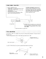
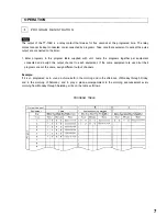
CHANNEL ASSIGNMENT switch-Set each
switch to ON when assigning all of B, C and D
channels to the A channel. When, for example,
the B channel switch is set to ON, the A channel
relay contact connects at the time programed for
both A and B channel. In this event, the B
control output does not work.
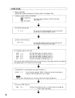
OUTPUT CHANNEL terminal
Output capacity : 24 V DC 0.5 A (resistance load)
Minimum load : 10 mV DC 10µA.
A relay contact connects for five seconds at the
programed time.
These relays are dry contacts.
Connect this terminal to start terminals of BGM
player or spot announcing machine, etc.
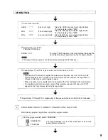
MEMORY BACK UP switch-Be sure to set this switch
to ON after installation. This switch protects clock and
stored programs for approximately 100 hours during
power outage.
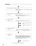
AC power inlet
Earth terminal-Be sure to ground unit.
RACK MOUNTING
To mount the TT-104B in an equipment rack, the rack mounting bracket (optional) is required. Follow the
procedures below.
1. After removing rubber foot of the TT-104B, attach the bracket to the TT-104B.
Fixing screw (3 x 8)
supplied with the bracket
Rack mount bracket
2. Fix the TT-104B in the rack using screws supplied with the bracket. See the figure.
Rack
Fiber washer
supplied with the bracket
Fixing screw (M5 x 12)
supplied with the bracket
5
Содержание TT-104
Страница 18: ...TOA Corporation Printed in Japan 133 05 276 50...


