


CFP-600L Conventional Fire Alarm Control Panel
- 9 -
9.5
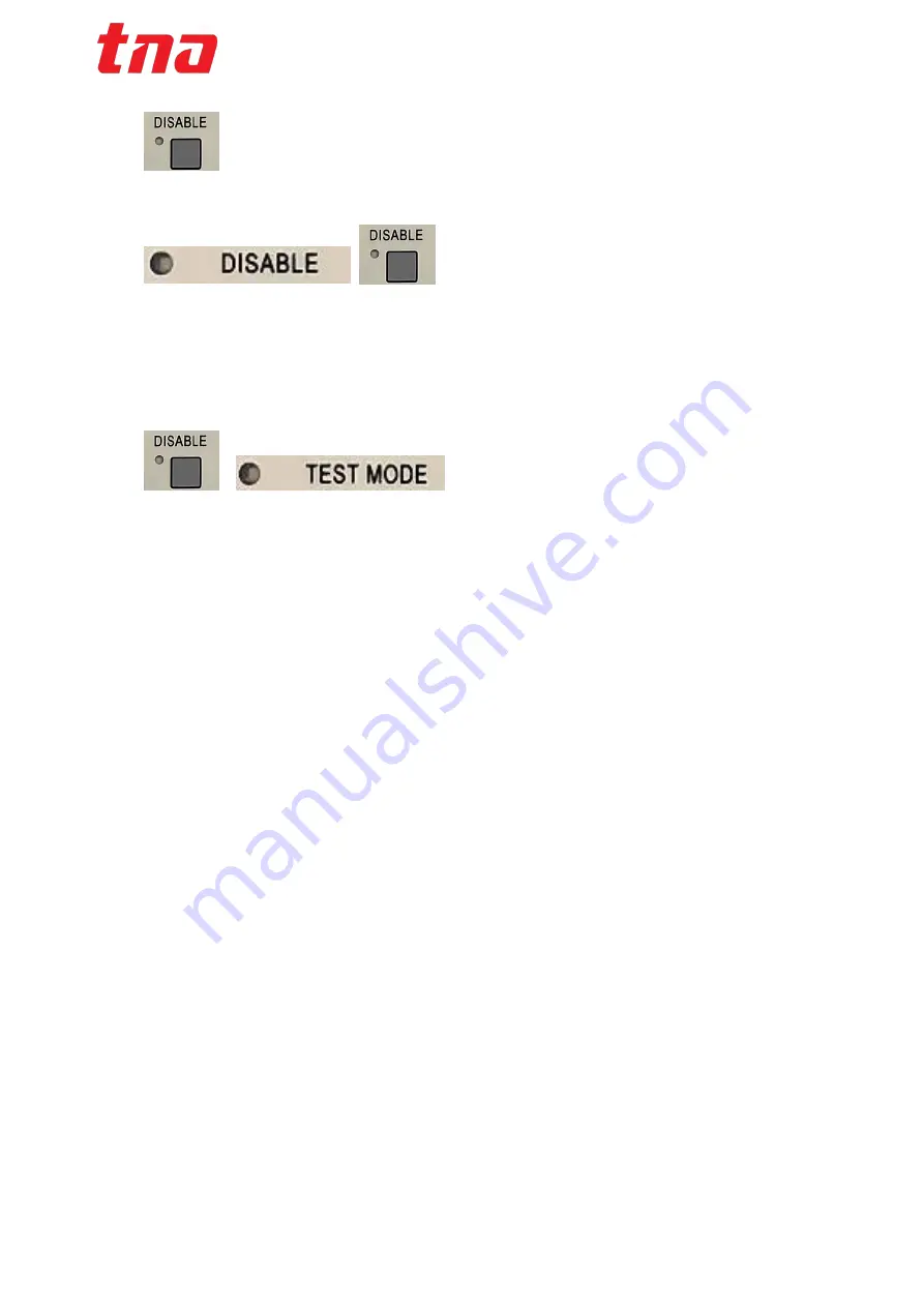
Disable / Enable
Press the Disable Button to disable a Zone.
Common disable indicator will light up along with the zone being disabled. Press the Disable button again
to enable the point.
9.6
Test
Press and hold the zone disable button for 3 seconds, you will notice the fault LED blinks quickly, next
release the button and zone disable LED will blink to indicate zone in test mode condition. Press and hold
the “zone disable” button again for 3 seconds to cancel test mode and switch off the zone Disable LED.
Zone in test mode will not activate the fire alarm outputs on the panel and modules when the circuit detects
a fire, however the panel will still register the Fire with the activation of visual and audible warnings to alert
the operator. Note this feature is only applicable for zone configured as Detector.
9.7
One Man Walk Test
Set
“Testing” jumper on the main display board to NC for one man walk test operation, it will prevent all
general outputs on the main terminal board and modules from activating when fire. The panel will continue
to register the fire and activate the sounders for 3 seconds, thereafter panel will reset automatically. This
feature will reduce the additional serviceman needed to standby at the panel to reset the panel after each
simulation test.