


USER MANUAL SAGA
Page 24 of 47
Connect accessory to multi-connector
The multi-connector inputs are labelled with ‘UNI’. Connect the connector of the
accessory to the correct input. Both the connector and the input on the Data
Recorder have a dot on them. Align the red marking on the multi-connector with the
orange dot adjacent to the multi-connector input of the Data Recorder. The UNI 1-
32 and UNI 33-64 connector are to be placed in each other’s opposite, e.g. the part
where the cables exit the connector face towards each other.
Connect bipolar electrodes
The bipolar inputs are marked with BIP. The connector of the accessory is white.
The corresponding receptacles on the Data Recorder are surrounded by a white ring.
Align the orange dot on the enclosure with the arrow on the bipolar connector. Do
not use excessive force to insert the connector. This may damage both Data
Recorder and accessory.
Connect auxiliary sensors
The auxiliary inputs are marked with ‘AUX’. The connector of the accessory is black.
The corresponding receptacles on the Data Recorder are surrounded by a black ring.
Align the arrow with the orange dot above the input on the Data Recorder. Do not
use excessive force to insert the connector. This may damage both Data Recorder
and accessory.
Connect digital sensor
The input for a digital sensor is marked with ‘DIGI’. The connector of the accessory
is nickel. Align the arrow with the orange dot above the input on the Data Recorder.
Do not use excessive force to insert the connector. This may damage both Data
Recorder and accessory.
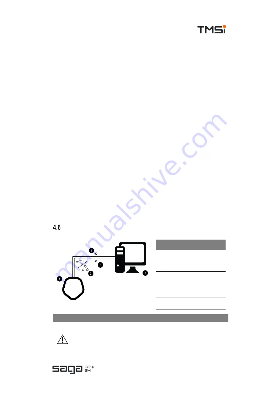
Data connections
Refer to
chapter 9
for used protocols, requirements and settings as applicable.
NOTE
In case of connecting SAGA to a LAN network via the ethernet interface, it is
recommended to use a secure, non-open network connection.
#
Description
1.
SAGA (Docking Station)
2.
Data acquisition PC
3.
Data connection of preference:
USB or Ethernet
4.
Control from PC to SAGA
5.
Data from SAGA to PC


