6
7
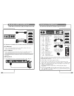
Connecting an Antenna or Cable
or
Cable Television
Network
Antenna
Input on the
TileVision
®
RF 1
RF 2
Sky™ digital receiver
TV 1
1
Connect the antenna or input cable to the
75Ω coaxial input
on the rear of the TileVision
®
.
2
If you are using an indoor antenna in the loft space, you may
need to turn it when tuning your television until you receive a
clear picture.
The connection to the Antenna/RF sockets on the TileVision
®
and
the Sky™ receiver must be made with both the TileVision
®
and the
Sky™ receiver disconnected from the mains supply.
Once the connections have been made, the Sky™ receiver must be
setup to supply power to the RF 2 socket as detailed below.
1
On the Sky™ remote control press
SERVICES
to show the
SERVICES menu.
2
Press the
4
button for the SYSTEM SETUP menu.
3
Press the
0
button, then the
1
button, then the
select
button, in
sequence, to display the INSTALLER SETUP menu.
4
Press the
4
button to select RF OUTLETS.
5
Press the
down
arrow to select RF Outlet Power Supply and
press the
left
or
right
arrows to change the setting to ON.
6
Press the
down
arrow to select Save New Settings and press
select
to save the settings.
7
Press the
sky
button to return to the previously viewed channel.
To view television channels correctly, a signal must be received by the set from one of
the following sources: an outdoor antenna, a cable television system or a satellite dish.
If a TileVision
®
is used with a Sky™ digital receiver which has two RF outputs, the channel can be
changed on the Sky™ receiver using the Sky™ remote control via the remote sensor on the TileVision
®
.
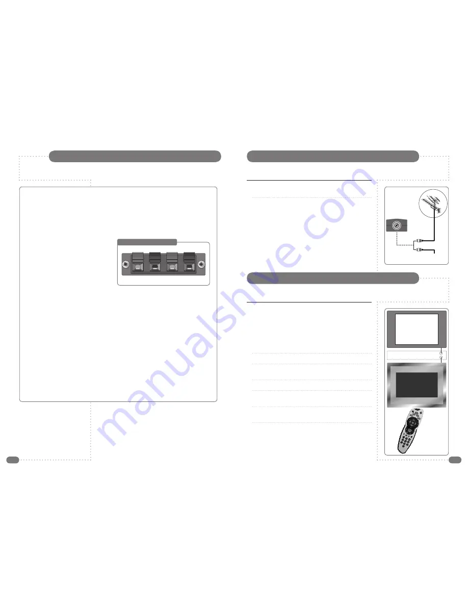
Connecting to your TileVision
®
Earthing Points
The Earthing connection points are found on the rear of the front plate and are clearly marked
with green labels. Connect the earthing cables from the back box to these points.
Power Socket
The Power socket (1) is located at the extreme left of the connection array.
Speaker Connections
The speakers should be connected after the
Earth straps to the rear of the front plate as
detailed on page 10 of these operating
instructions.
The speaker connection block is found on
the right of the rear of the front plate. Lift one
of the lugs, push one conductor of the
speaker lead into the connector, release the
lug and give the lead a slight pull to make
sure that it is gripped correctly. The other wires are connected in the same way.
Note: To ensure that the speakers are in correct phase, the conductor with the stripe should be
connected to the negative terminal (L– or R–) and the plain conductor should be connected to
the corresponding positive terminal (L+ or R+).
Connections to the speakers terminals should be made in the same way – striped conductor to
the negative terminal and plain conductor to the positive terminal.
Antenna Feed
The Antenna input jack is found at the extreme right of the connection array (refer to page 7).
A minimum signal level of 60dBu/1mV is required to avoid a noisy picture.
Additional connections
Connectors for; HDMI, SCART, S-VIDEO and Audio are found in the central portion of the
connection array. If these inputs are to be utilised the necessary cables must be installed at the
same time as the back box. COMPONENT video can also be connected via a suitable
COMPONENT to SCART adaptor (refer to pages 8 and 9 of these instructions).
Note: Careful consideration should be given to use of these inputs prior to the installation
of the unit.
Speaker Connection Block
L–
L+
R+
R–
☛
The signal level fed to the set must be at least
60dBu/1mV or the picture may be noisy.
If in doubt, consult a qualified aerial technician.
See page 29 for Active Antenna set-up.
Sky™ Remote Control Link Setup
☛
To set-up the Sky™ receiver to work with the
TileVision
®
you must use the Sky™ remote
control via the main TV (TV 1).


