4
5
TileVision
®
Connector Inputs
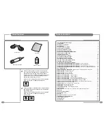
Please make sure the following items are
included with your TileVision
®
.
1
TileVision
®
glass front plate assembly – complete with Velcro
fixing strips
1
waterproof remote control
1
remote control holder
1
standard full function remote control
1
installation and instruction manual
1
mirror acrylic surround.
Your TileVision
®
Unpacking your TileVision
®
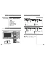
Remote control sensor and indicator
Power Indicator Status
Status
Stand-by
Power on
Remote control
Indicator
Red
Green
Red blinking
☛
If any items are missing,
contact your dealer.
POWER
ABC
DEF
GHI
JKL
MNO
WXYZ
TUV
PQRS
Sub-
Title
Info.
0
9
8
7
4
5
6
3
2
1
MENU
TV/AV
OK
SLEEP
ARC
PR
EPG
DTV
I/II
V
O
L
V
O
L
P P
FAV
LIST
TEXT
MIX
SIZE
INDEX
HOLD
REVEAL
TIME
UPDATE
PIP
INPUT
SWAP
PIP PR
MODE
POSITION
PICTURE SOUND
DTV
AUDIO PROFILE
510-301K
?
i
TV/AV
PR
VOL
MENU
TEXT
OK
EPG
P P
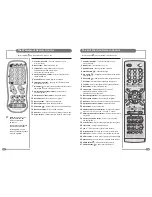
Full function
remote control
illustrated without
sliding cover
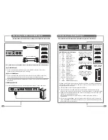
TV 17 Main Connector Array
DC12V Power In
HDMI (High Definition Multimedia Interface) In
S-VIDEO In
S-VIDEO Audio In (Left–White · Right–Red)
EURO-SCART – (RGB, FB, AV In, AV Out)
SVC Port – connect for service only
Internal Antenna
Antenna Input 75 Ω
1
2
3
4
6
5
7
8
1
2
3
4
5
6
7
8
12VDC
S-Video
HDMI
Audio
L
R
EURO-SCART
Internal Antenna
SVC Port
Antenna Input
TV 23 Main Connector Array
DC24V Power In
HDMI (High Definition Multimedia Interface) In
S-VIDEO In
S-VIDEO Audio In (Left–White · Right–Red)
EURO-SCART – (RGB, FB, AV In, AV Out)
SVC Port – connect for service only
Internal Antenna
Antenna Input 75 Ω
1
2
3
4
6
5
7
8
1
2
3
4
5
6
7
8
24VDC
S-Video
HDMI
Audio
L
R
EURO-SCART
Internal Antenna
SVC Port
Antenna Input
The antenna should be connected to the TileVision
®
using the
Antenna Input (
8
) and not to the Internal Antenna connection
(
7
). This allows a Sky™ or Sky+™ remote control to be used to
change channel on the Sky™ digital receiver via the infrared
sensor in the TileVision
®
. See page 7 for more information.


