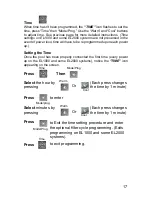
10
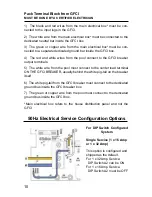
1) The black and red wires from the main electrical box* must be con-
nected to the input lugs in the GFCI.
2) The white wire from the main electrical box* must be connected to the
dedicated neutral bar inside the GFCI box.
3) The green or copper wire from the main electrical box* must be con-
nected to a separate dedicated ground bar inside the GFCI box.
4) The red and white wires from the pool connect to the GFCI breaker
output terminals.
5) The white wire from the pool must connect to the center load terminal
ON THE GFCI BREAKER, usually behind the white pig-tail on the breaker
itself
6) The white pig-tail from the GFCI breaker must connect to the dedicated
ground bus inside the GFCI breaker box.
7) The green or copper wire from the pool must connect to the dedicated
ground bus inside the GFCI box.
*Main electrical box refers to the house distribution panel and not the
GFCI
Pack Terminal Block from GFCI
MUST BE DONE BY A CERTIFIED ELECTRICIAN
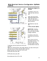
50Hz Electrical Service Configuration Options
For DIP Switch Configured
System
Single Service (1 x 16 Amp
or 1 x 32 Amp)
This option is configured and
shipped as the default.
For 1 x 32 Amp Service:
DIP Switch A2 can be ON
For 1 x 16 Amp Service.
DIP Switch A2 must be OFF
Содержание Premium EP-14
Страница 1: ...Part 11 0096 11...
Страница 2: ...This manual covers your new 2009 TidalFit...
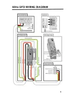
Страница 13: ...9 60Hz GFCI WIRING DIAGRAM...
Страница 57: ...INTERIOR SPA DIAGRAM 53...


