6
MSK110TH
+ MB100
Datum 24.09.2009
Art.Nr. 85210
Änd. Stand 271/09
Fig. 2
Fig. 3
Fig. 4
Fig. 5
Fig. 6: Definition of the counting direction with
magnetic strip and assemblage sensor/magnetic ring,
gap measure, tolerances
Gap sensor/magnetic strip
Maximum alignment error
active side
Travel direction
Direction of
outgoing cable
Signal
A before B
0.1mm ... 0.4mm
< 1°
< 3°
< 3°
Admissable devi-
atoion middle of
tape/sensor:
±2mm
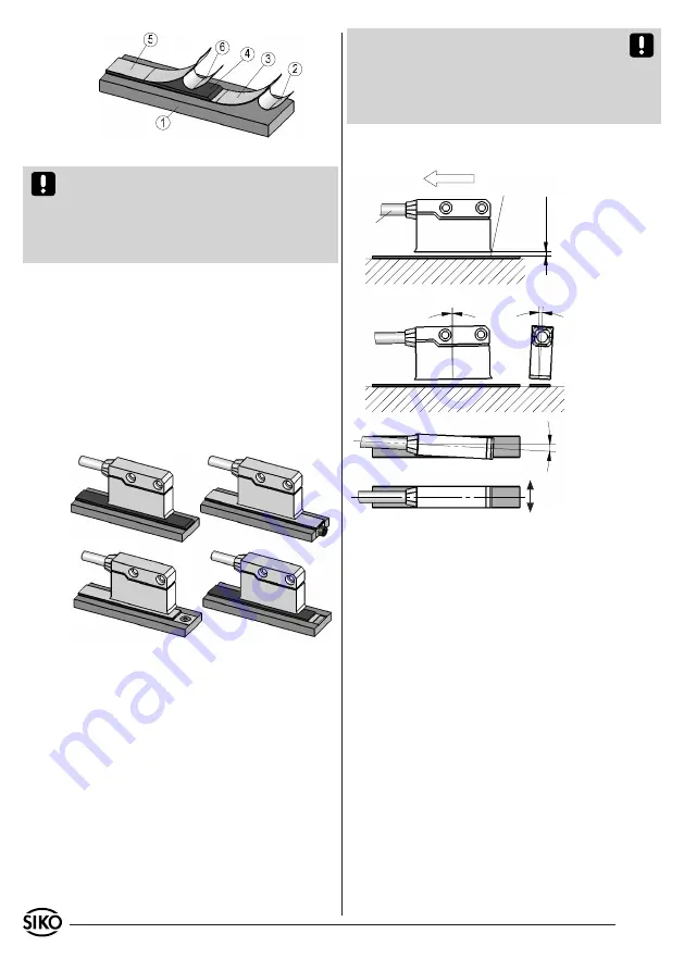
Fig. 1: Mounting of the magnetic strip
Attention!
Do not expose the system to magne-
tic fields. Any direct contact of the magnetic strip
with magnetic fields (eg. adhesive magnets or
other permanent magnets) is to be avoided. Sen-
sor movements during power loss are not captured
by the follower electronics.
Mounting examples
Mounting with chamfered ends (fig. 2) is not re-
commended unless the strip is installed in a safe
and protected place without environmental influ-
ences. In less protected mounting places the strip
may peel. There we recommend mounting accord.
to fig. 3 and 4.
Mounting in a groove (fig. 5) best protects the
magnetic strip. The groove should be deep enough
to totally embed the magnetic strip.
Attention!
The tolerance and gap measures must
be observed over the whole measuring length.
The max. gap without cover strip is 0,4mm. When
using cover strip, the gap is reduced by the thick-
ness of cover strip including its adhesive tape.
Sensor must not touch the magnetic strip.
LINEAR
application
MSK1000 with MB100
:
3.2 Mounting of the magnetic sensor MSK110TH
The magnetic sensor MSK110TH can be fastened
by using two bolts M3 over the elongated holes.
We recommend to use the enclosed fixing screws
and washer springs (fastening torque 1Nm).
Cables should be layed in such a way that there
is no danger of damaging. Provide ten-sion relief
and drag chain or casing, if necessary.
Observe the correct alignment with regard to
the counting direction (Fig. 6). This does not
apply if the counting direction can be reversed
in the electronic interpretation (e.g. in SIKO's
magnetic-strip displays).
•
•
4. Electrical connection
Wiring must only be carried out with power off!
Check all lines and connections before switching
on the equipment!
Interference and distortion
All connections are protected against the effects
of interference.
The location should be selected
to ensure that no capacitive or inductive in-
terferences can affect the sensor or the con-
nection lines!
Suitable wiring layout and choice
of cable can minimise the effects of interference
(eg. interference caused by SMPS, motors, cyclic
controls and contactors).
Necessary measures
Only screened cable should be used. Wire cross sec-
tion is to be at least 0,14mm², max. 0,5mm².
Wiring to the screen and ground (0V) must
be secured to a good point. Ensure that the
•
•
•
•
Содержание Drive DAB530
Страница 1: ...ThyssenKrupp Aufzugswerke Operating Manual Drive DAB530...
Страница 3: ......
Страница 62: ......
Страница 63: ......
Страница 64: ......
Страница 65: ......
Страница 66: ......
Страница 67: ......
Страница 68: ...ThyssenKrupp Aufzugswerke GmbH...
Страница 69: ...ThyssenKrupp Aufzugswerke GmbH...
Страница 70: ...ThyssenKrupp Aufzugswerke GmbH...
Страница 71: ......
Страница 72: ......
Страница 73: ......
Страница 74: ......
Страница 75: ......
Страница 76: ......
Страница 77: ......
Страница 78: ......
Страница 79: ......
Страница 80: ......
Страница 85: ......


