


Page 32
ETN043886-D02
K-Cube NanoTrak Auto-Alignment Controller
5.5 Programmed Operation - NanoTrak
5.5.1 A Typical Alignment using the NanoTrak
1) In the NanoTrak GUI, set the ‘Scan Circle Diameter’
control to approximately mid-position.
2) Press the ‘Latch’ button to select Latch mode and check that the Latch indicator LED is lit.
3) Click and drag to center the scan circle in the display.
4) Press the ‘Auto’ button to select ‘Auto’ mode. Ensure that the ‘Auto’ LED is lit.
5) Adjust the actuator on the positioning stage such that the fibers are spaced well apart, with zero power transmission
between them. (Alternatively, switch off or obscure the optical power source). Make a note of the bar graph displays of
relative power input and range. Since the optical source has been removed, only background noise is registered.
6) Use the actuators to bring the fiber tips together, until the display shows a significant increase indicating that the power has
risen above the background level.
7) Press the ‘Track’ button to select Track mode. Check that the ‘Tracking’ indicator is lit and that the circle moves towards
the position of maximum power (center screen). The NanoTrak has now positioned the fiber to give the maximum optical
power transmission.
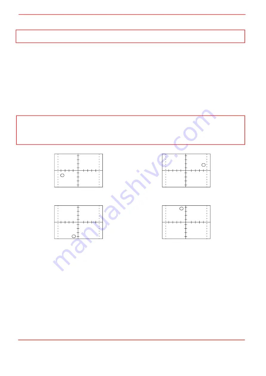
Fig. 5.6 NanoTrak displays and actuator adjustments
5.5.2 Using Two NanoTraks in the Same System
The NanoTrak scanning process uses a single frequency (and a highly selective discriminator similar to a radio receiver). It is
possible to use more than one NanoTrak controller in a single optical path (and with a single detector). For example, with two
control units set to different scanning frequencies (e.g.30 Hz and 40 Hz) it is possible to couple fibers both into (master
NanoTrak) and out of (slave NanoTrak) an integrated optical device such as a waveguide – see Fig. 5.7. The scan frequency
and input source can be set either via the application software
(see API Helpfile)
or directly via the Settings panel – see Section
5.4.1.
To set up a two NanoTrak system:
1) Make connections as shown in Fig. 5.7.
2) Power up the NanoTrak units.
3) Run the software.
4) In the master NanoTrak GUI, select ‘Settings’.
5) Select the ‘Tracking’ tab, then set the Circle User Frequeny, e.g. 40 Hz.
6) Select the ‘Input/Output’ tab, then set the Input Signal Source to ‘PIN (TIA)’.
Note
Familiarize yourself with NanoTrak operation from the GUI panel before attempting programmed operation from the Controller PC.
Note
If the circle reaches the edge of the display, this means that the piezo actuators cannot move far enough to reach the position
of maximum power. The horizontal and vertical actuators should be adjusted to bring the circle away from the edge of the
screen – see Fig. 3.8.
If the circle tends to drift, increase the scan circle diameter, if the circle tends to oscillate, decrease the scan circle diameter.
Decrease horizontal actuator
Decrease vertical actuator
Increase horizontal actuator
Increase vertical actuator
Содержание NanoTrak KNA-IR
Страница 47: ...www thorlabs com ...


