www.THORav.us | [email protected] | (763) 999-4253
™ & ® 2018 THOR AV. © 2022 THOR AV.
DATA CONNECTION
Generally, one data port on the processor supports up to about 525,000 pixels, depending on system
solution.
If data redundancy is required, each Primary Data Run needs an additional (redundant) data cable; using
two data ports on the processor.
When mapping the processor, verify the perspective view defined by the software. With a different
perspective selected, the mapping direction will be reversed.
Maximum recommended CAT6 cable length is 100 meters. Fiber transport is utilized for distances
exceeding 100 meters.
Connect LED panels to the processor data ports with cables provided.
Connect control PC / laptop via the Ethernet/USB port to the processor.
Connect a video source to the processor’s video input.
Data Redundancy
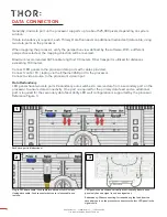
LED panels have two data ports. Redundancy auto switches to receive data from a secondary port on the
processor to ensure data connectivity. One port is required for the primary data feed and an additional
port is required for the secondary data feed. Verify LED wall configuration is supported by the processor.
Reference Figure 3.
Each data port is bidirectional.
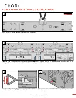
LED panels can be chained vertically or horizontally. Be sure each
panel only has one signal in and one signal out.
Redundancy: When connecting for redundancy, the feed from the
secondary port on the processor connects to the last LED panel in the
signal chain.
Plug in CAT6 data cable: Push cable into data port until it clicks.
Unplug data cable: Push connector button to release cable and
remove.
3
1
2
24

