


ITC222 Geometry & Convergence Procedures
12
Geometry
O
VERVIEW
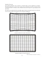
Although a convergence pattern is available internally successful geometry alignment depends on
a good external test pattern with center crosshair and outer border lines in both 2H and 2.14H scan
rates. (Using the component inputs may be easier as it is the only analog input capable of both
scan rates.) Alternately the component inputs may be used for the 2.14H pattern input and either
the baseband or RF inputs used for 2H.
NOTE:
As with other Thomson chassis, the service menu will make adjustments on the
scan rate that is currently onscreen. In other words if the onscreen display is 2H, when the
service mode is entered all adjustments will be performed in the 2H mode. However, if the
“Input” button is used to change the video input, a different scan mode could be entered.
Pay attention to which scan mode is currently being adjusted and make certain that scan
mode is not accidently changed.
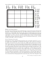
The geometry service menu has the alignments listed in the recommended order they should be
performed. There are also several that default settings and probably not require adjustment in
PTV instruments. All adjustments are listed below with their functions and default values.
Title
Default
Description
V-Slope (480P Only) B0
Vertical Slope adjusts center value of Vert IC inputs
V-Amplitude
68
Vertical Amplitude adjusts height of vertical raster
V-Position
A0
Vertical Position adjusts the up/down position of the raster
V-Linearity
60 (Default) Adjusts raster Vertical linearity. If Geometry linearity is close,
this should not be adjusted.
H-Position
AC
Adjusts the right/left video location on the raster.
H-Amplitude
64
Adjusts the raster width
EW-Amplitude
AC
Adjusts the EW Amplifier strength


