ITC222 Geometry & Convergence Procedures
27
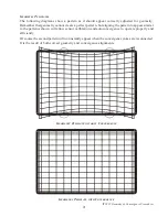
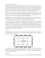
clues as to how to correct the issue without completely redoing geometry and convergence.
If the flattened side of the adjustment is to the right, one of two things is occurring. First, geometry
may be misadjusted too far to the left. Chances are other adjustments will also rail in that direction.
It may take some experimentation but using the centering rings move the entire raster for that
color to the right about 1/2”. This of course will probably require complete reconvergence of the
red raster, however it should resolve the railed adjustment. If the flattened side is on the left
geometry is probably too far to the right. The same occurs with the up/down alignments. If the
flattened side is on the top, the raster for that color is too far down. If it is on the bottom, the raster
is too far up. Use the centering rings to move the entire raster up or down about 1/2”. The rule of
thumb is to move the raster the
same direction
as the flat part of the pattern. And always remember
that if this is occurring in only one color, DO NOT ADJUST GEOMETRY!!! Geometry will
affect all three colors equally possibly causing the need for readjustment of the other two colors.
Carefully use the centering ring for the affected color for readjustments.
Always recheck sensor calibration any time geometry or the centering rings are changed for any
reason. If sensor calibration fails after moving the centering rings, compromise the original
movement until it completes successfully once again. Once the amplifiers regain additional range,
convergence may proceed. The same procedure may be used regardless of whether more than one
flattened area is noted as long as the flattened patterns are in the same direction.
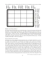
If a flattened area occurs in different directions, correction becomes complex and problems in the
original geometry setup are indicated. That is because the centering ring trick may be used
successfully for only one CRT and one direction at a time. However if flattened areas go in different
directions, raster size problems are indicated and global geometry adjustments must be used. Those
adjustments affect all three colors exactly the same amount and at the same time.
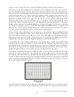
For example if the flattened areas are on different sides of the centerline and point away from the
centerline the raster is too narrow. But using the horizontal width control to increase the width
also increases the width of the two colors that may not be experiencing the same issue. Care must
be taken to change the width enough to gain adjustment headroom without causing sensor calibration
to fail. Conversely if the patterns flatten to the inside towards the center line the raster is too wide.
Horizontal width must be decreased.
Adjust Geometry Slightly to
Increase Width
The same is true if patterns are flat either side of the horizontal center line. If they point to each
other, vertical size is too tall. If they point away from the center line vertical size is too narrow.


