ITC222 Geometry & Convergence Procedures
8
So the proper steps when replacing an SSB module are:
1. Use Chipper Check (Appendix A) to either move the original SSB alignments or place the
default SSB file into the replacement module.
2. Use the Field Service Menu to load the default geometry and convergence files and set the
“Tube Type”.
3. Unless a CRT has also been replaced, make no mechanical adjustments to the CRT and DO
NOT MOVE THE CENTERING RINGS!
4. Refer to the section on Geometry procedures to properly align Geometry but if only one or
two CRT’s have been replaced it is not recommended to change any geometry alignments.
5. Converge the set using the Field Service Convergence Menu following the Convergence
Procedures.
C
ONSUMER
C
OMPLAINT
Most consumer complaints will center on convergence errors rather than geometry. Consumer
complaints of poor convergence and/or autoconvergence failure should be treated as separate issues.
Geometry errors can adversely affect sensor calibration, which in turn will cause autoconvergence
failure. If autoconvergence fails during the Sensor Calibration routine, suspect geometry errors,
particularly if failure occurs on the first (red) sensors. If all red sensors are located properly it
indicates geometry is most likely OK but gross convergence errors are causing autoconvergence
failures.
Always determine from the consumer if convergence was ever acceptable. If it was, but has drifted
too far off for autoconvergence to bring in successfully, carefully observe the screen before doing
anything. Convergence errors, some less than 1/4”, can drift in over time and may be too far out
for autoconvergence to successfully return to an acceptable condition. In most cases errors of this
nature may be manually returned to acceptance using FSM convergence menu. The only screen
required for these types of errors is Level 3 (15 x 13). Refer to Convergence Procedures for
detailed instructions on manual convergence.
If sensor calibration completes successfully and convergence is close but autoconvergence fails,
suspect one or more of the outer points, those adjustment locations located outside the frame
perimeter, are too far off to allow convergence to bring it in. This is the most difficult scenario as
the points cannot be seen. The failure location and careful observance of the screen may provide
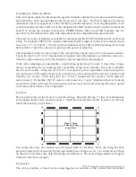
a clue as to where the pattern is off. For example, in the next screen,


