


A
PPENDIX
B, F
IELD
S
ERVICE
M
ENU
42
PRELIMINAR
Y
^
UP
^
DOWN
< > SELECT/CHANGE
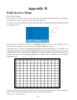
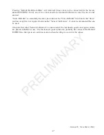
EVENT HISTORY
Return
Clear Event Codes
Code
11
24
78
51
00
Count Unit
00 1
01 2
00 3
00 1
00 0
Time Stamp
00 0135:30
00 0090:10
00 0043:54
00 0001:20
00 0000:00
Test: Brightness
Sensor: 2
Color: R
Scan Mode: 2H
E
VENT
H
ISTORY
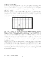
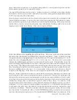
The Event History is where all errors are stored and available to the technician. There is a specific
section for the Sensor Calibration errors. Notice the Test information rectangle. There are two
tests performed during sensor calibration. First the video block luma (brightness) levels are set
for enough brightness to overcome ambient room light and intra-cabinet reflections. For this test
the sensor “luma level” is measured first with the CRT’s cut off setting the “dark” level. Then a
single video block is generated fully covering the sensor. The video luma level is adjusted high
enough to overcome ambient light yet not so bright it creates reflections inside the cabinet. If the
routine fails at any point, a full red screen will be immediately flashed, the routine will return to
the Convergence Menu and the failure error code will be logged into the Event History. Several
things may be discovered by checking these errors.
The brightness levels are set for each of the eight sensors in each color, first green, then red, then
blue. At the start, geometry DAC’s are collapsed by several notches to reduce the effects of overscan
bringing the video block closer to being centered on top the sensor. Green of course is affected less
than red or blue. So if green does not pass the luma test it is probable there is too much ambient light.
Move the cabinet out of direct lighting and try the routine again. However it is also possible
geometry is too far off to allow the video block to cover the sensor. If green passes, but red or blue
fails (and a visible video block can be seen), the most likely issue is incorrect geometry, not luma
levels. Remember that when green passes the luma test, the sensors and the sensor system are
working and may be eliminated as a cause of failure. It also means ambient light has been
compensated for and there is enough brightness to trigger the sensors. While excessive ambient
lighting is still possible, as long as the first pass is made successfully it is unlikely.
The sensor number on the error code corresponds to the same location identified in the previous
sensor location chart. The sensor that fails is a good indication of which geometry adjustment
could be incorrect. In this case sensor 2, the upper middle sensor did not see the video block. That
probably means vertical size is too short or too tall. By running the routine again and paying
attention to whether the video block is visible it can be reliably determined whether to increase or
decrease vertical size. If the block is seen onscreen, vertical size is too small and should be
increased at least 2 steps. The routine should then be run again. Most failures will be due to
horizontal or vertical size being incorrect since position, both horizontal and vertical are easier to
determine with the internally generated convergence pattern. However as a hint, if sensor 2 now
passes but sensor 7 fails, chances are vertical size was OK before, but vertical position was too far