background image

7

Connecting the Interface Box to the PC

Using the parallel cable, locate the printer port on the PC and connect the 25-pin Din connector
to it.  The other end of the printer cable (Centrex connector) connects to the interface box.
This is the only connection between the PC and the interface box.

Next, connect the serial cable to the interface box and to the appropriate adapter.  The
appropriate adapter depends on what chassis is being serviced.  Do not connect the adapter
or cable to the instrument being serviced until instructed to do so by the Chipper Check
software.  Each chassis is different on the setup and connection point.  Information on setup
and hookup is found in the Help files of the Chipper Check program.

CCII Install Software

The Chipper Check software is always changing.  To make sure you have the latest version,
go to www.thomsonnetwork.net.  Under “Order Chipper Check”, the latest version of software
will be shown and available for download.  If you already have the latest, there is no need to
download this version.  If not, then download the latest version.

Once downloaded, double click on the EXE file and it will self install.  Very little user interface
is required for installation.  Just follow the on-screen prompts and when done, the PC will
need to be restarted.  Restart is necessary because registry information is changed during
the install and in order for those changes to take effect it requires the computer be restarted.
Once the PC is restarted, Chipper Check software is ready for use.

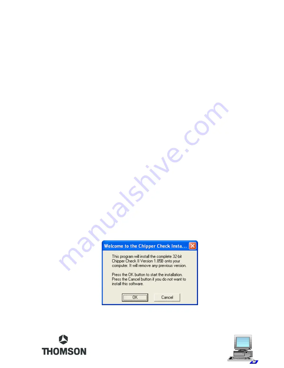
The first screen to come up is the Welcome screen.  This screen is the “are sure you want to
install” screen.  Options are OK or Cancel.  OK will start the installation and Cancel will stop
the installation.

If your updating a previous version of CCII, the install software will automatically remove any
previous version of Chipper Check.

Содержание Chipper Check II

Страница 1: ...Chipper Check II User Manual...

Страница 2: ......

Страница 3: ...edures 16 Procedure 16 Dead Set 18 CTC195 197 203 Setup Procedures 19 Procedure 19 Dead Set 20 Setup MM101 MM102 CTC210 CTC211 and LCOS Chassis 20 Procedure 21 PTV Convergence Setup 21 Dead Set 21 Set...

Страница 4: ...Check II hardware consists of several items The hardware items are Chipper Check II interface box Interface Cables serial and parallel cables TECI1 Adapter Board and Cables 2 Legacy Adapter Boards ITC...

Страница 5: ...are backwards compatible Chipper Check II Interface There are two types of interface boxes the modified CF002 and CF003 Atri level interface is the only one that is compatible with current chassis The...

Страница 6: ...connecting different cables for the different chassis The switch is for convergence communications on PTV products Because of their separate bus lines the convergence communications requires a connect...

Страница 7: ...version go to www thomsonnetwork net Under Order Chipper Check the latest version of software will be shown and available for download If you already have the latest there is no need to download this...

Страница 8: ...s started and the progress is displayed for reference only by the following graphic When all the files are copied to the destination folder a screen is displayed indicating the default port is LPT1 Th...

Страница 9: ...Chipper Check program from The last window displayed will indicate that changes have been made to the computer registry and the PC will need to be rebooted before the changes will take effect This is...

Страница 10: ...Servicer Information entry screen allows the Servicer to personalize their version of Chipper Check Options are Fill in all information and click on the OK button This will prevent this entry screen f...

Страница 11: ...the three has to be completed before the program will allow other tabs to be selected The options are 1 Open file 2 Save file 3 Enter Model and Serial numbers If only generic model and serial numbers...

Страница 12: ...y requirement would be locating the correct file and restoring it to the customers set The Model and Serial number fields are the best way to distinguish between instruments Because of this the model...

Страница 13: ...escribed below When the auto detection does not work the chassis will usually shut down and may have to be unplugged before it will power up again Manually putting the instrument into the service mode...

Страница 14: ...has a Motorola or ST microprocessor U3101 U3101 is marked with either ST or Motorola If the IC is a Motorola ground pin 1 if the IC is marked ST ground pin 2 Retain this ground while the EEPROM is bei...

Страница 15: ...he chassis Adapter board 212121 7 jumper wires and an IC clip are used to connect the Chipper Check interface box to the EEPROM You may connect leads directly to the EEPROM or use an IC clip The IC cl...

Страница 16: ...ill not be able to control the volume Once the instrument is in the service mode it is not possible to adjust the volume from the front panel or remote control When the instrument is in the service mo...

Страница 17: ...isplay the ROM version and P 00 V 00 b Using the remote hand unit or the front panel button press and hold the volume until the V value is 200 c Now press the Channel up button to enter the service mo...

Страница 18: ...up screen with a Dead Set button 6 Click on the Dead Set button to open up the chassis selection buttons 7 Select the appropriate chassis button 8 Connect the adapter to the instrument chassis 9 Plug...

Страница 19: ...ith this requirement may cause the instrument to shut down Once the instrument is placed into the service mode the main microprocessor is placed into the slave mode It will not respond to any remote c...

Страница 20: ...n KK 6 Dead Set 1 RemoveAC power from the instrument by disconnecting theAC power cord 2 Click on the Dead set button in the main screen 3 Select the correct TV chassis for the instrument being tested...

Страница 21: ...Chipper Check interface box 3 Turn the computer on and start the Chipper Check software DO NOT select chassis at this time 4 Connect the adapter board to the service connector J13202 of the I O board...

Страница 22: ...When the service mode is entered manually on the DTV306 or DTV307 the DM module will not respond to FPAkey presses or IR remote control commands When the service mode is entered automatically by conn...

Страница 23: ...O board The ground switch is necessary because the ground of the convergence module can not be connected to the ground of the I O board without shifting convergence If convergence is set with the swit...

Страница 24: ...ct the TECI1 adapter and connect it to the Chipper Check interface box 3 Select the correct adapter cable for the television you will be communicating with and plug it into the TECI1 adapter ATC221 us...

Страница 25: ...hernet computers without a hub and has the send and receive wires crossed You cannot use a standard Ethernet cable to connect the PC to the DM module Establishing a connection 1 Plug the Ethernet Cabl...

Страница 26: ...r Check s Ethernet Communications with the TV Once the user has selected the type of DM module used in the TV the Chipper Check software will attempt to communicate over the Ethernet CROSSOVER cable c...

Страница 27: ...ted to a network write down the original IP address so that you can change the settings back when finished Pressing OK will display a Warning to reboot the PC Communication can not be estiblished unti...

Страница 28: ...CCAB3684 371 Legacy adapters CCAB2121 and CCAB2117 are only available for a limited time in the complete kit CC1K They are replaced by the TECI1 and cable kit as well Dead Set 1 RemoveAC power from th...

Страница 29: ...y The remaining circuitry is tested by using external jumpers and the 212121 adapter board used with CTC195 197 203 or the TECI1 and Cable adapter The components required to do all diagnostic tests ar...

Страница 30: ...sion with daughter board installed NOTE the new interface box CF003 has the extra circuitry If there is a failure one or more of the following will be displayed Detect EEPROM This routine test the EEP...

Страница 31: ...s be performed prior to running the Check clock lines and Check IM_Enable tests because those tests rely on the data lines Screen shots for this routine are All 5 outputs high or low There are 5 outpu...

Страница 32: ...make sure it is high or low based on the test being run Screen shots for this routine are Check timing The Check Timing routine toggles the standby data line 200 000 times and puts a 10 KHz square wav...

Страница 33: ...llel Port Make sure the correct port is selected in the options tool bar for the one connected to the Chipper Check interface Failure to connect to thecorrectportwillresultinaninterfacefailureunderthe...

Страница 34: ...pper Check CCF002 upgrade kit CCF002 is no longer available You will need to buy Chipper Check II available on line at Thomson Network Chipper Check is not communicating with this TV has worked with o...

Страница 35: ...9 CTC188 198 and CTC185 Used for CTC210 211 CTC203 DTV306 307 MM101 102 CTC195 197 ITC008 ITC222 ATC311 LCOS Used for ATC311 ATC321 ATC322 and ATC323 Includes all DLPs with Ethernet connection Used fo...

Страница 36: ...R e g a m a D g n i p p i h S t n e g A y r e v i l e D o t r e f e R s t r a P s t r a P s t r a P s t r a P s t r a P t c e r r o c n i d e v i e c e r t r a P d e r e d r O t r a p r o t u b i r t...

Страница 37: ......

Страница 38: ...TTCCIIUM...

Отзывы: