Thermo Scientific HyPerforma DynaDrive 500 L Скачать руководство пользователя страница 3

3

2.  Close the E-Box and lock the panel using a  

flat-head screwdriver before continuing.

3.  Connect all electrical plugs to facility power. Refer 

to hardware/electrical labels and schematics to 
ensure proper electrical voltage is connected to 
the DynaDrive S.U.B. 

Note:

 The yellow plug and 

receptacle are for 120 VAC, and the blue plug and 
receptacle are for 240 VAC S.U.B.s.

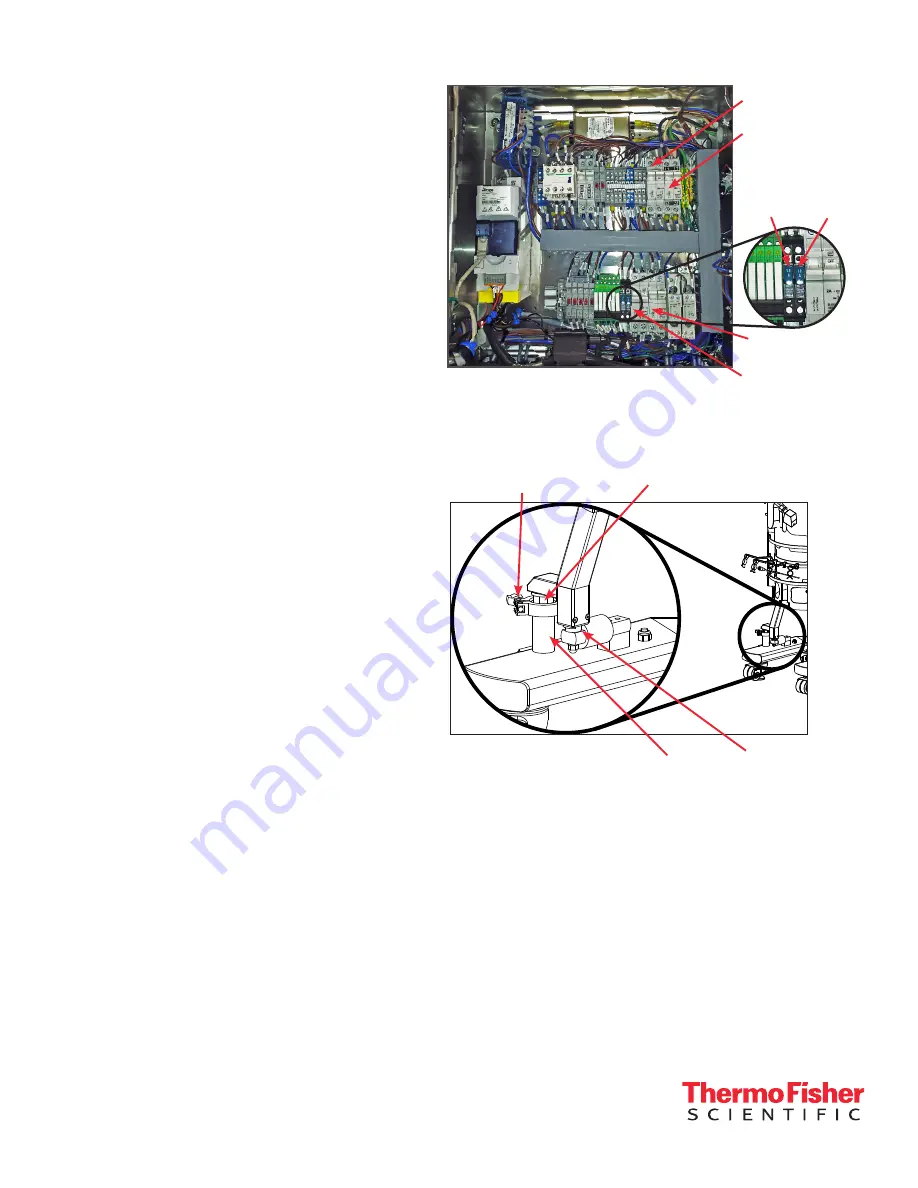
Unlocking load cells

Figure 3 illustrates the location and components of load 
cells on on a standard HyPerforma S.U.B. The location 
and process is the same for DynaDrive S.U.B.s. 

All load cells must be fully locked down in order to 
move the DynaDrive S.U.B. For DynaDrive S.U.B. 
hardware units purchased with factory-installed load 
cells, the load cells are shipped in the locked position 
(threaded up) for equipment protection.

1.  To unlock the load cells (after the system is in its 

final location), remove and discard the delrin slip 
ring if it is present. Remove the tri-clamp. 

2.  Loosen the lockout nut, using an adjustable or 

1.25 in. wrench (not supplied), until the nut is tight 
against the base or leg of the S.U.B. Repeat this 
process for each load cell until all of the lockout 
nuts are disengaged from the lockout posts. Do 
not reinstall the tri-clamp.

3.  At this point, the DynaDrive S.U.B. hardware is 

ready to be prepared for BPC loading.

Leveling and connecting the system

All manual movements of the DynaDrive S.U.B. 
hardware should be over smooth surfaces, with the 
S.U.B. empty and disconnected from all power and 
gas/feed sources. All load cells must be fully locked 
down in order to move a S.U.B.

1.  Verify that the facility electrical supplies are 

sufficient to support the power requirements of the 
DynaDrive S.U.B. and ancillary components, such 
as controllers or pumps.

VFD breaker

Continuous power 
breaker

Temp. 
display 
breaker

Main power 
breaker

E-Stop power 
breaker

Pressure 
sensor 
breaker

Figure 2. DynaDrive S.U.B. E-Box interior.

A

Figure 3. Load cell schematic.

Lockout nut

Delrin slip 

ring

Lockout 

post

38.1 mm (1.5 in.)

Tri-clamp

Содержание HyPerforma DynaDrive 500 L

Страница 1: ...d not be moved by pulling of any kind The Thermo Scientific HyPerforma DynaDrive S U B may not be installed in a potentially explosive atmosphere as set forth in the applicable EU ATEX Directive It is the responsibility of the end user to review and understand the potential dangers listed in the ATEX 2014 34 EU guidelines Static electricity may build up in BPCs BioProcess Containers BPCs may act a...

Страница 2: ...erated under traditional eukaryotic cell culture conditions A general understanding of bioreactor systems and their operation is important prior to using the system for the first time Read and understand this user s guide before operating failure to do so could result in injury and potential loss of product Only trained operators should be allowed to operate the equipment For complete warnings saf...

Страница 3: ... ring if it is present Remove the tri clamp 2 Loosen the lockout nut using an adjustable or 1 25 in wrench not supplied until the nut is tight against the base or leg of the S U B Repeat this process for each load cell until all of the lockout nuts are disengaged from the lockout posts Do not reinstall the tri clamp 3 At this point the DynaDrive S U B hardware is ready to be prepared for BPC loadi...

Страница 4: ... jacket Figure 4 The inlet is typically on the right side if you are facing the connectors refer to the permanent labels on the inlet and outlet lines Figure 4 Attaching water jacket port using a tri clamp Note Refer to the TCU manufacturer s guidelines for detailed TCU setup information 10 Use the tri clamp fitting to attach the water jacket inlet outlet ports to the bottom of the outer support c...

Страница 5: ...se a safety cutter to carefully open the outer polybag Figure 10 Take care to not damage the BPC Figure 12 Pushing button on hub cover Figure 13 Hub cover opened Figure 14 Raising BPC lift lever Figure 6 Slitting open taped sides of the BPC box Figure 7 BPC secured to cardboard insert in box Figure 8 Carefully lifting out the BPC Figure 9 Folding up flaps on the insert 5 While another operator hol...

Страница 6: ...ngaged by attempting to push the lever back up If the hub is not locked the hub will fall out and the arm will raise 12 Locate the bottom hub at the bottom center of the BPC Pull the hub toward the center cutout at the bottom front of the outer support container Once the hub is aligned with the correct cutout slide it toward the back of the DynaDrive S U B until you feel it shift into place Figure...

Страница 7: ...the front linesets to keep them from tangling use the motor lift controller see the user s guide DOC0090 for information on using the motor lift controller to raise the pneumatic motor lift Figures 23 and 24 After raising the motor lift to its highest position turn the lock dial on the motor lift controller Note The controller cannot be locked unless the motor lift has been fully raised Figure 23 ...

Страница 8: ...ot rated as a pressure vessel DO NOT EXCEED 34 mbar 0 5 psi within the BPC or the system could fail causing personal injury or damage to equipment DO NOT leave the BPC unattended while inflating Consult your sales representative for recommended air flow rates The operating pressures at the level of the DynaDrive S U B are of primary importance and these values must be adhered to 22 Check the BPC t...

Страница 9: ...e air before this is possible 25 While the BPC continues filling with air remove all bubble wrap and polybags from the line sets 26 Remove the polybag from the drain line set position the line clamp as close as possible to the BPC port and then close the clamp Use a cable tie around the clamp to ensure it does not open 27 Remove the plastic insert located in the thermowell if present 28 Insert the...

Отзывы: