Form: 2435-3
Arctic Installation and Operation Manual
Revision: 10
P/N 105641-01
Date: 12-1-2018
Thermal Solutions, 1175 Manheim Pike, Lancaster, PA 17601
Web:
Phone:
717-239-7642
Fax:
877-501-5212
Email:
42
CAUTION
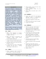
Do Not Overdrive Tubes! Overdriving tubes can cause damage to the tubes and boiler
header holes. Use only approved Thermal Solutions tube driver and specified hammer. The
end-formed tube fitting is designed to deform if overdriven to minimize damage to the
vessel tube holes.
8.
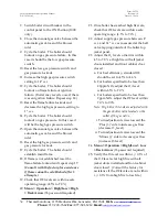
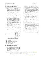
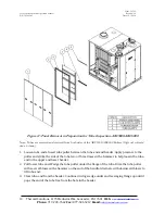
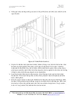
Reinstall the tube clamps. Replace the nuts and flat washers if damaged in any way. Use brass
nuts only! Tighten the nuts until snug. Do not try to compress the tube-ends into the holes with
the clamps, because the clamps might break or the stud might shear.
9.
Refill the boiler. Fill the unit with water and ensure that there is no leakage at the replacement
tube-ends before reinstalling the flue collector panels.
WARNING
If a leak is detected after a replacement tube has been installed, pressure in the boiler must
be reduced to zero before adjusting tube(s). Adjusting tubes under pressure could result in
serious personal injury.
10.
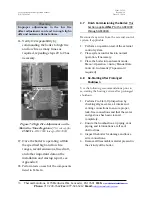
Reinstall all flue access doors, door clamps, and jacket panels.
11.
Perform startup check prior to putting boiler back into operation.
5.6
Safety and Operating Controls
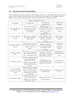
All of the safety control devices listed in Table 17 are logically linked to the Concert Boiler Control
that supervises the sequence of operation of the boiler for safe and efficient operation. It does so by
ensuring proper light off and firing of the main burner and if need be, will immediately cut-off gas
supply to the main burner when gas pressure, water temperature, water flow or another critical
attribute is outside of the operational settings. It also varies the combustion rate in real time to meet
the desired load of the system.
WARNING
Do not install, operate, service or repair any components of this equipment unless you are
qualified and fully understand all requirements and procedures. Trained personnel should
refer to those who have completed Thermal Solutions Service School training specific to this
product.
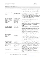
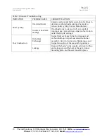
Table 17: Safety and Operating Controls
Component
Function
Power
Switch
If this switch is in the off position, power is interrupted to the control circuit of the boiler,
which prevents the boiler from operating. If the switch is in the on position, power is
supplied to the control circuit.
Automatic
Reset
Operating
Aquastat
If the boiler water temperature exceeds the adjustable set point, power is interrupted to the
control circuit of the boiler, which prevents the boiler from operating. When the boiler water
temperature drops below the set point minus the adjustable differential setting, power is again
supplied to the control circuit.

